


5-52 Cisco 7010 Hardware Installation and Maintenance
Installing and Configuring Processor Modules
Tools Required
You need the following tools to complete this procedure:
•
Number 1 Phillips or 3/16-inch flat-blade screwdriver
•
3/16-inch nut driver
•
Wrist strap or other grounding device to prevent ESD damage
Removing the FSIP
Two or four port adapters (each port adapter provides two ports) are installed on each FSIP at the
factory, so in order to install a new port adapter (or to replace an existing one), you need to remove
an existing port adapter. Each four-port module on an FSIP is driven by a CPU; four-port FSIPs
contain one processor, and eight-port FSIPs contain two processors. You cannot add additional ports
to a four-port FSIP to upgrade it to eight ports.
Follow these steps to remove and replace the FSIP:
Step 1
Disconnect all network interface cables attached to the FSIP ports.
Step 2
Put on a grounding strap and attach the equipment end to one of the captive installation
screws on the rear of the chassis.
Step 3
Use a screwdriver to loosen the two captive installation screws on the FSIP.
Step 4
Place your thumbs on the upper and lower ejector levers and simultaneously push the top
lever up and the bottom lever down to release the FSIP from the backplane connector.
Step 5
Grasp the FSIP handle with one hand and place your other hand under the carrier to support
and guide the FSIP out of the slot. Avoid touching the board.
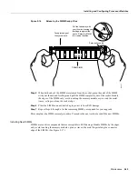
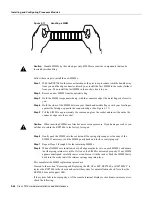
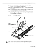
Step 6
Carefully pull the FSIP straight out of the slot, keeping your other hand under the carrier to
guide it. (See Figure 5-2.) Keep the FSIP at a 90-degree orientation to the backplane.
Step 7
Place the removed FSIP on an antistatic mat or antistatic foam and proceed to the section
“Removing Port Adapters.”
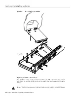
Removing Port Adapters
Port adapters are installed on each FSIP at the factory. You must remove an existing port adapter in
order to replace or install a new one. Each port adapter is anchored to the FSIP with two double-row
vertical board-to-board (BTB) connectors and two Phillips-head screws that extend down into the
standoffs. (See Figure 5-18.) The port adapter is also anchored to the carrier faceplate with four
jackscrews with lock washers (two per port).
Caution
The surface-mounted components on the port adapters are extremely susceptible to ESD
damage. Keep each port adapter in a separate antistatic bag until you are ready to install it. Always
wear a ground strap and handle boards as little as possible. When you must handle the board, limit
contact to the board edges only, avoiding contact between the board and clothing.
To remove a port adapter from the FSIP perform the following steps:
Step 1
Ensure that the FSIP is resting on an antistatic mat or on antistatic foam. You should still
be wearing an ESD-prevention ground strap.
Step 2
Position the FSIP so that it is in the same orientation as shown in Figure 5-18.
Summary of Contents for TelePresence Server 7010
Page 10: ...x Cisco 7010 Hardware Installation and Maintenence ...
Page 14: ...iv Cisco 7010 Hardware Installation and Maintenance Document Conventions ...
Page 148: ...3 36 Cisco 7010 Hardware Installation and Maintenance Using the Flash Memory Card ...
Page 158: ...4 10 Cisco 7010 Hardware Installation and Maintenance Troubleshooting the Processor Subsystem ...
Page 242: ...5 84 Cisco 7010 Hardware Installation and Maintenance Replacing Internal Components ...
Page 258: ...A 16 Cisco 7010 Hardware Installation and Maintenance MIP Interface Cable Pinouts ...
Page 270: ...B 12 Cisco 7010 Hardware Installation and Maintenance Interface Processor LEDs ...
Page 274: ...C 4 Cisco 7000 Hardware Installation and Maintenance ...
Page 287: ...Index 13 ...


