C H A P T E R
Installing the Router 3-1
3
Installing the Router
This chapter provides the following procedures for installing the router, making all external cable
connections, turning on the system power, and verifying that the system initializes properly:
•
Installing the chassis in an equipment rack (optional) or on a table top
•
Installing the cable management brackets (optional but strongly recommended)
•
Making external connections
•
Starting up the router
The rack-mount kit provides the hardware for mounting the chassis in a standard 19-inch-wide
equipment rack or in a Telco-type rack. If you are installing an equipment shelf or using mounting
hardware other than that supplied with the chassis, review the guidelines in the section “Equipment
Racks” in the chapter “Preparing for Installation,” then proceed to the section n “General
Installation” in this chapter after the router is installed in the rack. A cable management kit is also
included with the chassis. Install these fixtures to keep network interface cables untangled and
orderly, and to maintain clear access to interface processors in the lower interface processor slots.
Rack-Mounting the Chassis
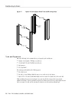
The rack-mounting kit included with the router is for a standard 19-inch, two- or four-post rack or a
two-post Telco-type rack. The chassis mounts to two rack posts with ears that attach to the sides of
the chassis. The inside width between the two posts or mounting strips (left and right) must be at least
17.72 inches. (See Figure 3-1.) The chassis ears attach to either the front or back of the chassis, so
that you can position either the interface processor or noninterface processor end at the front of the
rack. Install the cable management fixtures after you install the chassis in the rack.
Some equipment racks provide a power strip along the length of one of the mounting strips.
Figure 3-1 shows a typical 19-inch equipment rack with a power strip along one of the back posts. If
your rack has this feature, consider the position of the strip when planning fastener points and ensure
that you will be able to pull processor modules straight out of the slots. Also, if you plan to install
the cable management brackets, ensure that the power strip does not block the sides of the brackets
and prevent you from routing the cables through them. When possible, install the interface processor
end of the chassis away from the power strip to avoid problems accessing cables and interface
processors. (See the section “Equipment Racks” in the chapter “Preparing for Installation.”)
The inlet and exhaust ports for cooling air are located in the sides of the chassis, so multiple routers
can be stacked in a rack with little or no vertical clearance. If necessary, you can remove the four
chassis feet. The chassis is 10.50 inches high when the feet are removed.
Summary of Contents for TelePresence Server 7010
Page 10: ...x Cisco 7010 Hardware Installation and Maintenence ...
Page 14: ...iv Cisco 7010 Hardware Installation and Maintenance Document Conventions ...
Page 148: ...3 36 Cisco 7010 Hardware Installation and Maintenance Using the Flash Memory Card ...
Page 158: ...4 10 Cisco 7010 Hardware Installation and Maintenance Troubleshooting the Processor Subsystem ...
Page 242: ...5 84 Cisco 7010 Hardware Installation and Maintenance Replacing Internal Components ...
Page 258: ...A 16 Cisco 7010 Hardware Installation and Maintenance MIP Interface Cable Pinouts ...
Page 270: ...B 12 Cisco 7010 Hardware Installation and Maintenance Interface Processor LEDs ...
Page 274: ...C 4 Cisco 7000 Hardware Installation and Maintenance ...
Page 287: ...Index 13 ...


