

Installing Cisco TelePresence System Profile 55” Dual
Page 2
78-20440-01 Profile 55 Dual Installation Sheet | 2011 OCTOBER | © 2011 Cisco Systems, Inc. All rights reserved.
6
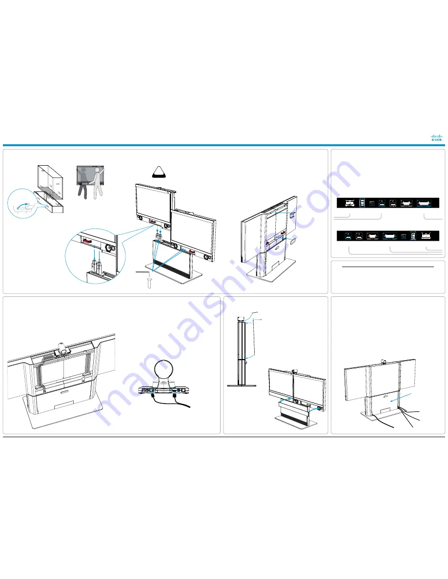
mounting the camera cables and the camera
1.
Locate the camera cables in the bottom module (the two long
cables).
2.
Locate the hole in the monitor where the cables can be
pushed through. Push the cables through the hole in the right
monitor.
3.
On the rear side, place the cables in the foam rails that are
going on the rear side of the monitor.
CAMERA CABLE CONFIGURATION
PrecisionHD 1080p
HDMI
RJ45
For countries with 60 Hz current frequency
you must set the PrecisionHD 1080p camera
DIP switch to: 00100.
4.
Connect the RJ45 and HDMI cables to the camera, see
illustration.
5.
Place the camera and slide it towards the front.
6.
Place the camera cables in the foam rails.
Upper monitor
bracket
Lower monitor
bracket*
* The lower monitor bracket is not used on a wall
mounted system. Instead, make sure the monitors
are aligned at the front.
8
connecting the system
Ethernet cable
PC cable
Microphone cable
Power cable
1.
Open the rear door and lead the cables
out through the openings at the lower
part of the door.
2.
Close the rear door carefully. Take care
not to shut the cables in the door.
3.
Place the PC cable and the
microphones on the table.
4.
Connect the Ethernet cable.
5.
Connect the power cable (use the
provided country specific cable).
6.
Open the front door and turn on the
monitor.
7.
Follow the instructions in the
accompanying Touch 8” installation
guide to connect and initialize the touch
interface device.
8.
The system should be up and running
in a few minutes.
The rear door
Open the front door and locate the monitor connectors and cables. Connect the cables
as illustrated below.
Connect the left monitor:
1.
HDMI cable
2.
Speaker in, 15 pin D-SUB cable
(tighten the screws)
3.
Power cable
Connect the right monitor:
1.
HDMI cable
2.
Speaker in, 15 pin D-SUB cable
(tighten the screws)
3.
Power cable
4
unpacking the monitor box and lifting out the monitors; fastening the monitors to the bottom module
LIFTING HANDLES. Locate the
orange lifting handles in the front
and rear side of the monitor.
1.
Carefully lift the right monitor out of
the packaging as illustrated.
2.
See the two triangle holes in the
monitor base. Use these holes to
help guiding the monitor to enter the
poles on the column.
3.
Repeat the above procedure for the
left monitor.
Right monitor
Left monitor
Triangular holes to
guide the monitor
Allen key
4 * M8
×
15
Unpack the
monitor box.
Lift out to open
the snap lockers.
caution
heaVy
7
mounting the back cover and top lid, and finishing up
1.
Hook on the back cover in the
slots at the top and snap it in place
with the lower magnets.
The magnets are strong. Make
sure your fingers are not trapped.
2.
Fasten the back cover with two
M4
×
15 bolts and nuts (tool: Allen
key).
3.
Slide the top lid into position and
snap it tight with the magnets.
4.
Remove the plastic foils
from the screen and the
monitor frame.
5.
Snap on the two speaker
grilles.
6.
Use the supplied cloth to
clean the system.
4.
Align the monitors at the top and fasten the two monitors
together using the upper monitor bracket and the M4
×
25
screws.
5.
Fasten the two monitors together at the bottom using the
lower monitor bracket and the M4
×
8 screws.
6.
Fasten the monitor to the column poles using
four M8
×
15 screws, two screws at each monitor.
7.
Tighten the monitor gently to the bottom module until the
monitor cannot be moved anymore.
Back cover
Top lid
5
connecting the monitor cables to both monitors
left monitor connectors
Power
HDMI 1
Speaker in
right monitor connectors
Power
HDMI 1
Speaker in
emc a class declaration
warning:
This is a class A product. In a domestic environment this product may cause
radio interference in which case the user may be required to take adequate measures.
A
级声明
(A Class product declaration)
本产品为
A
级
ITE
,在其使用说明,铭牌等显著位置中已包含如下内容的声明
(We declare here that the subject product is A class ITE product, and the
following statement is clearly marked in the user manual or nameplate):
声明所在位置
(Position of the Declaration):
使用说明
User Manual
铭牌
Nameplate
申请号
(Application No.)
:
申请人
(Applicant):
型号
(Model Number)
:
签字
/
盖章
Signature/Stamp:
日期
Date:
警告
此为
A
级产品。在生活环境中,该产品可能会造成无线电干扰。在这种
情况下,可能需要用户对干扰采取切实可行的措施。
WARNING:
This is a class A product. In a domestic environment this
product may cause radio interference in which case the user may be
required to take adequate measures.


