background image


5-25

Cisco SCE 2000 4xGBE Installation and Configuration Guide

OL-7824-07

Chapter 5      Connecting the Management Interfaces and Performing Initial System Configuration

Connecting the Management Interface

Connecting the Management Interface 

The SCE platform is equipped with two RJ-45 management (MNG) ports. These ports provide access 
from a remote management console to the SCE platform via a LAN. The two management ports provide 
the possibility for a redundant management interface, thus ensuring management access to the SCE 
platform even if there is a failure in one of the management links.

If only one management port is used, the desired port is simply connected directly to the LAN. If both 
management ports are used, they must both be connected to the management console via a switch. In this 
way, the IP address of the MNG port is always the same, regardless of which physical port is currently 
active.

The procedures for cabling the management port and testing connectivity between the SCE 2000 and the 
remote management host are explained in the following sections:

  •

Cabling the Management Port, page 5-25


  •

Verifying Management Interface Connectivity, page 5-26


Cabling the Management Port  

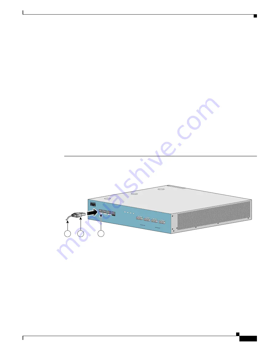
The SCE 2000 has two management ports, labeled Mng1 and Mng 2.

Step 1

Take the Ethernet cable provided (with attached RJ-45 connector) and plug it into the desired MNG port 
on the front panel of the SCE 2000, as shown in 

Figure 5-2

.

Figure 5-2

Cabling the Management Port

Step 2

Connect the other end of the Ethernet cable into your management network.

  •

If only one management port is used — connect the port directly to the LAN.

  •

If both management ports are used — connect both ports to the LAN via a switch.

Make sure that you push on the RJ-45 connector attached to the cable until you hear a click, which 
indicates that the connector is fully inserted and secured in the receptacle. Gently pull on the plug to 
confirm whether the plug is locked into the socket.

LINK RX

Cisco SCE 2000 

Series

4xGBE

TX

RX

MM

TX

LINK RX TX

RX

MM

TX

LINK RX TX

RX

MM

TX

LINK RX TX

RX

MM

TX

GBE-1

SUB

LINE

NET

PWR B STAT

US

PWR A

BYPASS

10/100/

1000

LINK/

ACTIVE

10/100/

1000

LINK/

ACTIVE

GBE-2

SUB LINE/CASCADE

NET

AUX

CONSOLE

MNG 2

MNG 1

92791

3

2

1

Summary of Contents for SCE 2000

Page 1: ... Inc 170 West Tasman Drive San Jose CA 95134 1706 USA http www cisco com Tel 408 526 4000 800 553 NETS 6387 Fax 408 527 0883 Cisco SCE 2000 4xGBE Installation and Configuration Guide Release 3 5 5 July 27 2009 Text Part Number OL 7824 07 ...

Page 2: ...e Cisco logo Cisco Lumin Cisco Nexus Cisco Nurse Connect Cisco Stackpower Cisco StadiumVision Cisco TelePresence Cisco Unified Computing System Cisco WebEx DCE Flip Channels Flip for Good Flip Mino Flip Video Flip Video Design Flipshare Design Flip Ultra and Welcome to the Human Network are trademarks Changing the Way We Work Live Play and Learn Cisco Store and Flip Gift Card are service marks and...

Page 3: ...e Control Solution 1 1 Service Control for Broadband Service Providers 1 2 Cisco Service Control Capabilities 1 2 The SCE Platform 1 3 Information About Management and Collection 1 4 Network Management 1 5 Subscriber Management 1 5 Service Configuration Management 1 6 Data Collection 1 6 C H A P T E R 2 Introduction to the SCE Platform 2 1 Introduction 2 1 Information About The SCE Platform 2 1 Fr...

Page 4: ...3 8 Information About Two Cascaded SCE 2000s For Dual Links 3 9 Two Cascaded SCE 2000s Inline Topology 3 9 Topology Related Parameters 3 11 Connection Mode Parameter 3 12 sce id Parameter 3 12 Priority 3 12 On Failure Mode Parameter 3 13 C H A P T E R 4 Installation and Maintenance 4 1 Introduction 4 1 Information About Preparing to Install the SCE 2000 Platform 4 1 Tools and Parts Required 4 2 In...

Page 5: ... the Fan Module 4 21 Replacing the Fan Module 4 22 How to Replace the Battery 4 22 C H A P T E R 5 Connecting the Management Interfaces and Performing Initial System Configuration 5 1 Introduction 5 1 How to Set Up the Local Console 5 1 Initial System Configuration 5 3 Setup Command Parameters 5 4 Step 1 How to Configure Initial Settings 5 6 Step 2 How to Configure the Hostname 5 7 Step 3 How to S...

Page 6: ...ew the Gigabit Ethernet Counters 6 9 What to Do Next 6 10 Information About Cascaded Systems 6 10 How to Install a Cascaded System 6 10 CLI Commands for Cascaded Systems 6 11 Topology Related Parameters for Redundant Topologies 6 11 How to Configure the Connection Mode 6 12 How to Set the Link Mode 6 12 Monitoring a Cascaded System 6 13 How to Install a Service Control Application 6 14 C H A P T E...

Page 7: ...bleshooting 8 1 Introduction 8 1 Troubleshooting Overview 8 1 Information About Troubleshooting Tools 8 2 CLI Commands for Troubleshooting 8 3 Checking the LEDs 8 4 Problem Solving Using a Subsystems Approach 8 6 Identifying Startup Problems 8 6 Troubleshooting the Power Subsystem 8 7 Troubleshooting the Firmware Package Installation 8 8 Troubleshooting the Management Subsystem 8 9 Troubleshooting...

Page 8: ...A 4 How to Cable the External Optical Bypass Module A 5 Specifications A 7 A P P E N D I X B CLI Commands to Verify a Successful Installation B 1 Introduction B 1 Basic Post Installation Checklist B 1 CLI Command Output Samples B 3 show version B 3 show interface B 4 show system operational status B 4 show interface linecard B 4 show interface linecard connection mode B 4 show interface linecard l...

Page 9: ...the installation and basic configuration procedures covered in this guide you will then use the appropriate companion publications to more completely configure your system This guide contains instructions on how to install and run the SCE 2000 platform This guide assumes a basic familiarity with telecommunications equipment and installation procedures Audience This guide is for the networking or c...

Page 10: ...t OL 7824 02 2 5 7 August 2005 Complete reorganization and revision of product documentation Table 2 Document Organization Chapter Title Description 1 General Overview page 1 1 This chapter provides a brief introduction to Cisco Service Control 2 Introduction to the SCE Platform page 2 1 This chapter provides a hardware overview of the SCE 2000 platform 3 Information About Topology page 3 1 This c...

Page 11: ...ser Guide To view Cisco documentation or obtain general information about the documentation refer to the following sources Obtaining Documentation Obtaining Support and Security Guidelines page xiii The Cisco Information Packet that shipped with your SCE 2000 platform 6 Cabling the Line Ports and Completing the Installation page 6 1 This chapter provides instructions for cabling the Gigabit Ethern...

Page 12: ... bold font Commands and keywords and user entered text appear in bold font italic font Document titles new or emphasized terms and arguments for which you supply values are in italic font Elements in square brackets are optional x y z Required alternative keywords are grouped in braces and separated by vertical bars x y z Optional alternative keywords are grouped in brackets and separated by verti...

Page 13: ...ded aliases and general Cisco documents see the monthly What s New in Cisco Product Documentation which also lists all new and revised Cisco technical documentation at http www cisco com en US docs general whatsnew whatsnew html Subscribe to the What s New in Cisco Product Documentation as a Really Simple Syndication RSS feed and set content to be delivered directly to your desktop using a reader ...

Page 14: ...xiv Cisco SCE 2000 4xGBE Installation and Configuration Guide OL 7824 07 About this Guide ...

Page 15: ...Service Control Concept The Cisco Service Control Solution page 1 1 Service Control for Broadband Service Providers page 1 2 The Cisco Service Control Solution The Cisco Service Control solution is delivered through a combination of purpose built hardware and specific software solutions that address various service control challenges faced by service providers The SCE platform is designed to suppo...

Page 16: ...ity planning Provide customer intuitive tiered application services and guarantee application SLAs Implement different service levels for different types of customers content or applications Identify network abusers who are violating the Acceptable Use Policy Identify and manage peer to peer NNTP news traffic and spam abusers Enforce the Acceptable Use Policy AUP Integrate Service Control solution...

Page 17: ... programmable network devices is capable of performing application layer stateful flow inspection of IP traffic and controlling that traffic based on configurable rules The SCE platform is a purpose built network device that uses ASIC components and RISC processors to go beyond packet counting and delve deeper into the contents of network traffic Providing programmable stateful inspection of bidir...

Page 18: ...the following management components to manage all aspects of the solution Network management Subscriber management Service Control management These management interfaces are designed to comply with common management standards and to integrate easily with existing OSS infrastructure Figure 1 2 LINK RX Cisco SCE 2000 Series 4xGBE TX RX MM TX LINK RX TX RX MM TX LINK RX TX RX MM TX LINK RX TX RX MM T...

Page 19: ...S and the SCE platforms Subscriber information is stored in the SM database and can be distributed between multiple platforms according to actual subscriber placement The SM provides subscriber awareness by mapping network IDs to subscriber IDs It can obtain subscriber information using dedicated integration modules that integrate with AAA devices such as Radius or DHCP servers Subscriber informat...

Page 20: ... simple standards based approach makes it easy to manage multiple devices in a large network Service Control provides an easy to use GUI to edit and create these files and a complete set of APIs to automate their creation Data Collection The Cisco Service Control solution generates usage data and statistics from the SCE platform and forwards them as Raw Data Records RDRs using a simple TCP based p...

Page 21: ...he Shipping Container Contents page 2 5 SCE 2000 Installation Checklist page 2 7 The Service Control Engine SCE platform which is the hardware component of the Cisco Service Control solution is designed to support observation analysis and control of Internet IP traffic Table 2 1 summarizes model information for the SCE 2000 platform Front Panel The SCE 2000 Front Panel consists of ports and LEDs a...

Page 22: ...using an RS 232 cable with an RJ 45 connector as provided in the SCE 2000 kit AUX 1 RS 232 RJ 45 port used by technicians GBE ports 1 4 4 GigabitEthernet ports for connecting to the line and or cascading two devices CLI designation interface GigabitEthernet 0 1 through 0 4 LINK RX Cisco SCE 2000 Series 4xGBE TX RX MM TX LINK RX TX RX MM TX LINK RX TX RX MM TX LINK RX TX RX MM TX GBE 1 SUB LINE NET...

Page 23: ...ates that the system is booting up Flashing green indicates that the system is fully operational Flashing orange indicates that the system is operational but is in a warning state Red indicates that there is a problem or failure Note that Alarms are hierarchical Failure takes precedence over Warning which takes precedence over operational Bypass Continuous green indicates that the traffic bypasses...

Page 24: ...cate the operational status of the SCE 2000 line ports as follows Link Green indicates that the port link is up Unlit indicates that the port link is down Rx Flashing Green indicates that there are incoming packets Tx Flashing Green indicates that there are outgoing packets Mng The Mng port LEDs indicate the operational status of the SCE 2000 out of band LAN based management port as follows Link A...

Page 25: ...00 Back Panel DC Power Information About Checking the Shipping Container Contents Use the SCE 2000 Component List to check the contents of the SCE 2000 platform shipping container Do not discard the shipping container You need the container if you move or ship the SCE 2000 platform in the future BYPASS 2 IN POWER B OK IN POWER A OK BYPASS 1 1 2 3 4 92760 BYPASS 2 IN POWER B OK IN POWER A OK BYPASS...

Page 26: ...0 4xGBE platform configured with either AC or DC power supplies Accessories The following accessories might arrive in separate shipping containers Rack mount kit Two mounting brackets for 19 rack Six screws Phillips 8 32 x 3 8 for attaching the brackets to the SCE 2000 chassis supporting mounting brackets for 19 rack Two crossrail supports for 19 rack with front and back posts Management cables Fa...

Page 27: ...d Topology verified number of SCE 2000 platforms number of links and whether inline or receive only Installation Checklist copied Site log established and background information entered Site power voltages verified Site environmental specifications verified Required passwords IP addresses device names and so on needed for initial configuration available Required tools available Network connection ...

Page 28: ...2 8 Cisco SCE 2000 4xGBE Installation and Configuration Guide OL 7824 07 Chapter 2 Introduction to the SCE Platform Information About The SCE Platform ...

Page 29: ...mation About Topology Considerations page 3 2 The SCE 2000 Platform The SCE 2000 introduces a solution for dual links with load sharing and asymmetrical routing and support for fail over between two SCE platforms The SCE 2000 supports wire speed processing of full duplex 2 Gigabit Ethernet streams The SCE 2000 can therefore be deployed in a multi link environment either in a single or dual SCE pla...

Page 30: ...ent and configuration How many SCE 2000 platforms are needed and how will they be installed Physical topology of the system The actual physical placement of the SCE 2000 in the system Topology related configuration parameters The correct values for each parameter must be ascertained before configuring the system to make sure that the system will function in the desired manner Functionality The SCE...

Page 31: ...The SCE 2000 includes a Network Interface Card with a bypass mechanism that is enabled upon SCE 2000 failure In addition when connected in line it can also be enabled in normal operation to simultaneously bypass traffic flow to the other side and direct it internally for analysis In this case it maintains receive only like monitoring functions when control functionality is not required The bypass ...

Page 32: ...tbound traffic This problem is typically solved by connecting the two SCE platforms in cascade mode or through an MGSCP cluster thereby making sure that both directions of a flow run through the same SCE platform However this is sometimes not feasible due to the fact that the SCE platforms sharing the split flow are geographically remote especially common upon peering insertion In this type of sce...

Page 33: ... Inline Topology page 3 5 Dual link Inline Installation page 3 6 Single Link Inline Topology Typically the SCE 2000 is connected in a full duplex GBE link between two devices such as a router or BRAS When the SCE 2000 is installed as an inline installation it physically resides on the data link between the subscribers and the network Figure 3 1 Figure 3 1 Single SCE Platform Single Link In line To...

Page 34: ...ream packets go on the other link When installed in this topology the SCE 2000 completely overcomes this phenomenon and provides its normal functionality as if asymmetrical routing were not occurring in the two links Figure 3 2 Single SCE Platform Dual Link Inline Topology This topology supports both monitoring and control functionality and is referred to as inline connection mode LINK RX Cisco SC...

Page 35: ...latform Single Link Receive Only Topology When configuring the SCE 2000 an optical splitter topology is referred to as receive only connection mode Note that in an optical splitter topology the SCE 2000 only enables traffic monitoring functionality Note When implementing receive only topologies with a switch the switch must support SPAN functionality that includes separation between ingress and eg...

Page 36: ...phenomenon and provides its normal monitoring functionality as if asymmetrical routing were not occurring in the two links This installation supports monitoring functionality only and is configured as receive only connection mode Figure 3 4 SCE Platform Dual Link Receive Only Topology Note When implementing receive only topologies with a switch the switch must support SPAN functionality that inclu...

Page 37: ...line Topology page 3 9 Two Cascaded SCE 2000s Inline Topology This topology allows both control and monitoring functionality where redundancy is required and inline connection is used Figure 3 5 The two SCE 2000s are cascaded so the primary SCE 2000 processes the traffic of the two links while the secondary SCE 2000 only bypasses the traffic of its links to the primary SCE 2000 for processing and ...

Page 38: ...cessed there so the traffic processing continues for both the links The bypass of the traffic through the failed SCE 2000 is configurable and the user may choose to always cutoff the line that goes through the failed SCE 2000 In this case network redundancy protocols like HSRP are responsible for identifying the line cutoff and switching all the traffic to go through the functioning SCE 2000 LINK ...

Page 39: ...ded topologies defines which link is connected to this SCE platform The sce id parameter which identifies the SCE platform replaces the physically connected link parameter which identified the link This change was required with the introduction of the SCE8000 GBE platform which supports multiple links In the SCE 2000 the number assigned to the sce id parameter 0 or 1 will be defined as the of numb...

Page 40: ...y connection mode Two SCE 2000 inline installation Inline cascade connection mode Two SCE 2000 optical splitter installation Receive only cascade connection mode sce id Parameter A cascade topology supports two traffic links In the SCE 2000 this parameter defines which link is connected to which SCE8000 platform The name of the parameter refers to its use in the SCE8000 GBE platform for which it a...

Page 41: ...errupted Cutoff There is no forwarding of traffic The link is forced down resulting in traffic cutoff at Layer1 The Forwarding mode enables control of traffic flow and is not compatible with the non operational status In a single SCE 2000 topology the value of this parameter is determined by whether or not the link can be completely cut when the SCE 2000 fails or whether traffic flow should contin...

Page 42: ...3 14 Cisco SCE 2000 4xGBE Installation and Configuration Guide OL 7824 07 Chapter 3 Information About Topology Topology Related Parameters ...

Page 43: ...e SCE 2000 Platform page 4 4 Removing and Replacing a Power Supply Unit page 4 13 How to Replace the Power Supply Unit page 4 18 Reconnecting the Power page 4 18 Fan Module Overview page 4 21 How to Replace the Battery page 4 22 Information About Preparing to Install the SCE 2000 Platform Before installing your SCE 2000 platform you should consider the power and cabling requirements that must be i...

Page 44: ...ith your rack for mounting the SCE 2000 to the rack 12 AWG or 2 5 mm copper installation wire with hex or loop connectors for DC power leads Ring terminals must be UL approved and suitable for 12 AWG wire Level optional Tape measure optional Appropriate cables to connect the SCE 2000 to the network and console terminal Rack mounting kit optional A new AC input or DC input power supply A new fan mo...

Page 45: ...quately ventilated can cause system over heating In addition chassis panels made inaccessible by poor equipment placement can make system maintenance difficult Airflow page 4 3 Site Requirements page 4 4 Airflow Figure 4 2 displays the airflow through the SCE 2000 Figure 4 2 Airflow Through the SCE 2000 When you plan the location and layout of your equipment rack or wiring closet you need to consi...

Page 46: ...The kit provides the hardware needed see SCE 2000 Component List page 2 6 to mount the SCE 2000 in either of two types of standard 19 inch equipment rack 19 inch rack with only two posts in the front Use the supporting brackets included in the kit 19 inch rack with four posts two in the front and two in the back Use the crossrail supports included in the kit If you are not rack mounting your SCE 2...

Page 47: ...that no exhaust air from other equipment is drawn into the SCE 2000 For descriptions and illustrations regarding airflow see Airflow page 4 3 Do not place the SCE 2000 on the floor during installation Dust that accumulates on the floor is drawn into the interior of the SCE 2000 by the cooling fans Excessive dust inside the SCE 2000 can cause over temperature conditions and component failures Allow...

Page 48: ...tform firmly on the tabletop or workbench Remember to check for proper ventilation Allow at least 2 inches 5 cm on each side for proper ventilation and 5 inches 12 7 cm at the back for ventilation and power cord clearance What to Do Next Proceed to section How to Attach a Chassis Ground Connection page 4 11 to continue the installation Rack Mounting a SCE 2000 Platform You can mount the SCE 2000 p...

Page 49: ...osts or mounting strips left and right must be at least 17 3 inches 44 cm Note Remember to leave a two inch 5 cm clearance on both sides of the SCE 2000 and at the rear for adequate airflow for the inlet and exhaust vents Because the inlet and exhaust ports vents for cooling air are located at both sides of the chassis respectively multiple SCE 2000s can be stacked in a rack with no vertical clear...

Page 50: ...hing the Mounting Brackets 4 post Figure 4 7 Attaching the Mounting Brackets 2 post Step 3 Repeat steps 1 and 2 on the other side of the SCE 2000 This completes the steps for attaching the rack mount brackets to the SCE 2000 If mounting the SCE 2000 in a rack with only two posts skip to How to Mount the System to the Rack page 4 10 If mounting the SCE 2000 in a rack with four posts proceed to the ...

Page 51: ...ipment directly above and below it Step 1 Assemble the two crossrail supports as illustrated in Figure 4 8 Use three screws for each crossrail assembly Make sure that they are oriented so that both crossrails will support the SCE 2000 when they are attached to the rack Figure 4 8 Assembling the Slider Brackets Step 2 Align the crossrail supports with the side of the rack parallel to the floor Step...

Page 52: ...nting strips or posts on both sides of the rack A rack with both front and back posts will have the crossrail supports installed Slide the SCE 2000 onto these crossrails and push it all the way back Figure 4 9 Figure 4 9 Sliding the SCE Platform into the Rack Step 4 While keeping the brackets flush against the posts or mounting strips align the holes in the brackets with the holes on the rack or m...

Page 53: ...tails Note When installing the unit the chassis ground connection must always be made first and disconnected last Step 1 From the enclosed grounding kit remove the necessary materials the grounding cable green and yellow colored cable and pairs of hex nuts and spring washers Step 2 On the rear panel of the SCE 2000 locate the chassis grounding connector refer to the appropriate figure for an AC or...

Page 54: ...E 2000 4xGBE Installation and Configuration Guide OL 7824 07 Chapter 4 Installation and Maintenance Installing the SCE 2000 Platform Figure 4 11 Grounding the Unit AC IN POWER B OK IN POWER A OK BYPASS 1 210421 2 1 ...

Page 55: ...ate anti static guard measures The SCE 2000 includes an anti static wrist strap in the accessory kit Attach the copper tape strap to an unpainted metal surface on the chassis You may leave the strap connected to the chassis when your have finished Never install an AC power module and a DC power module in the same chassis Information About the Power Supply page 4 14 Powering Down the Power Supply U...

Page 56: ...ing the other power supply Each power supply has fans that cool the power supply unit These fans also help to cool the internal components of the SCE 2000 as they direct the air flow to the outside through vents in the rear of the power supply unit The faceplates of both power supplies have a handle an on off switch and one captive installation screw An AC input power receptacle is available on th...

Page 57: ... input power supplies the OK LED is used to monitor the power supply DC output voltages used to power the platform The normal operating ranges for the 12 VDC output voltage is between 11 9V and 12 1V If the output voltages are within normal operating ranges the green OK LED is illuminated If the 12 VDC output voltages are above more than 12 1V or below less than 11 9V normal ranges the OK LED is n...

Page 58: ...wer Down a DC Input Power Supply Unit and Remove the DC Input Leads page 4 17 Table 4 6 Power LED on front panel Status for AC input and DC input Power Supply Units LED State Power Supply Unit Condition Continuous green Corresponding power supply unit is present and functioning normally Red Corresponding power supply unit present but malfunctioning Unlit Corresponding power supply unit is either n...

Page 59: ... Note Before completing any of the following steps and to prevent short circuit or shock hazards ensure that power is removed from the DC circuit To ensure that all power to the power supply unit is OFF locate the circuit breaker on the panel board that services the DC circuit switch the circuit breaker to the OFF position and tape the switch handle of the circuit breaker in the OFF position Note ...

Page 60: ...ce your other hand underneath the power supply for support Step 2 Fit the groove in the side of the new power supply module into the guide in the chassis Step 3 Gently but firmly slide the module into the chassis until its faceplate is flush with the chassis rear panel Note When inserting a power supply into the SCE 2000 platform do not use unnecessary force slamming the power supply into the chas...

Page 61: ... IN and OK LEDs on the power supply unit and the corresponding Power LED on the front panel If the new AC input power supply unit is operating properly these LEDs will be glowing green Step 5 Ensure that the power supply is properly aligned and the installation screw is tightened How to Reconnect DC Input Power Supply Unit The following procedures explain how to reconnect a DC input power to the S...

Page 62: ...ds depends on the color coding of the DC power source at your site Make certain the lead color coding you choose for the DC input power supply matches lead color coding used at the DC power source Note Use 12 AWG 2 5 mm copper wire only with hex or loop connectors Ring terminals must be UL approved and suitable for 12 AWG wire Step 4 Using the number 2 Phillips screwdriver securely fasten the prot...

Page 63: ...ote that a fan failure is often audible Removing and Replacing the Fan Module page 4 21 Replacing the Fan Module page 4 22 Removing and Replacing the Fan Module The following sections explain how to remove and replace a fan module in a SCE 2000 platform Do not remove or install modules without using appropriate anti static guard measures The SCE 2000 includes an anti static wrist strap in the acce...

Page 64: ...t use unnecessary force slamming the fan module into the chassis can damage the connectors on the rear of the module Step 4 Seat the fan module in the SCE 2000 platform by tightening the two captive installation screws with a 1 4 inch flat blade screwdriver Note The fan module is not fully seated until you tighten the installation screws on the faceplate How to Replace the Battery The SCE 2000 has...

Page 65: ... to follow the sequence of procedures outlined How to Set Up the Local Console page 5 1 Initial System Configuration page 5 3 Connecting the Management Interface page 5 25 How to Set Up the Local Console Even if you will be managing the SCE 2000 from a remote location you must first connect the unit to a local console and configure the initial settings for the SCE 2000 to support remote management...

Page 66: ...nnect the other end of the serial cable with an attached DB 9 connector to the VT100 compatible local serial terminal Step 3 Make sure the local terminal is configured as a VT 100 terminal according to the fixed SCE 2000 CON port parameters Step 4 Press Enter several times until the Cisco logo appears on the local terminal and the setup configuration dialog is entered System Configuration Dialog A...

Page 67: ...e end of the dialog when approved by the user Therefore if the setup dialog is aborted no change takes place in the configuration other than time settings if entered When the dialog is complete you may review the new configuration before applying it The system displays the configuration including parameters that were not changed The system also displays any errors that are detected in the configur...

Page 68: ... password encryption Time Settings time zone name and offset Standard time zone abbreviation and minutes offset from UTC local time and date Current local time and date Use the format 00 00 00 1 January 2002 SNTP Configuration broadcast client status Set the status of the SNTP broadcast client If enabled the SCE will synchronize its local time with updates received from SNTP broadcast servers unic...

Page 69: ...rprise traps system administrator Name of the system administrator Topology Configuration Connection mode Is the SCE 2000 installed using inline topology or receive only topology using an optical splitter type of deployment Is this a cascade topology with two SCE 2000s connected via the cascade ports Or is this a single platform topology physically connected link cascade topology only In a cascade...

Page 70: ...ch as time date and SNTP settings form sub dialogs or menus within the setup dialog You may skip an entire menu thereby accepting all default values for the parameters within the menu Each group of related parameters is prefaced by a question asking whether you want to enter the menu To skip the menu answer no n to the question Would you like to enter the SNMP configuration menu n To abort the set...

Page 71: ...ed as the value of the MIB II object sysName The maximum length is 20 characters The default hostname is SCE 2000 Step 1 The current hostname is displayed To accept the displayed value press Enter To change the value type any desired character string and press Enter EXAMPLE Enter hostname SCE 2000 Step 3 How to Set the Passwords Configure the passwords as follows Set the password for each authoriz...

Page 72: ...rd encryption is not enabled To disable password encryption press Enter To enable password encryption type y and press Enter EXAMPLE Following is an example of changing all passwords Password encryption is not enabled default Enter a User password cisco userin Enter an Admin password cisco mng123 Enter a Root password cisco cistech Enable passwords encryption no Step 4 How to Configure Time Settin...

Page 73: ...r new local time and date 14 00 01 1 July 2002Time zone was successfully set The system clock and the calendar were successfully set Step 4 You are asked whether you wish to enter the SNTP configuration menu If you do not wish to configure the SNTP skip the rest of this section and go to To enter the SNTP configuration dialog type y and press Enter Would you like to enter the SNTP configuration me...

Page 74: ...nfigure SNTP unicast servers no y Enter IP address or hostname of SNTP unicast server 10 1 1 1 Step 5 How to Configure the DNS Settings The DNS configuration menu defines the IP address of the domain name server which is used for DNS lookup as well as the default domain name which is used to complete unqualified host names You may choose to skip the DNS configuration menu if you wish to accept all...

Page 75: ...ould you like to add another Name Server no Step 6 How to Configure the RDR Formatter Destination The SCE 2000 passes Raw Data Records RDRs to an external collection system via the RDR Formatter In order for the data to reach the correct location the IP address of the external collection system and its port number must be configured Step 1 Enter the RDR formatter configuration menu Would you like ...

Page 76: ...e management interfaces Note ACL 0 is a pre defined list that permits access to all IP addresses Configuration of access control lists is done in two stages 1 Create the access control lists You may create 99 ACLs with a maximum of 20 entries per list Each entry consists of an IP address and an indication of whether access is permitted or denied to this IP address 2 Assign the ACLs to the appropri...

Page 77: ... be added to the list The following list will deny access to IP address 10 1 1 0 but permit access to all others deny 10 1 1 0 permit any If no entry in the assigned Access Control List matches the connection or if the Access Control List is empty the default action is deny Step 1 Enter the Access Control Lists configuration menu Would you like to enter the Access lists configuration menu no y Typ...

Page 78: ...o default for this parameter Enter wildcard bits Step 7 The maximum number of entries in an ACL is 20 If the any option was used no other IP addresses may be added to the list To add more entries type y and press Enter Would you like to add another entry to this list no y Enter up to 20 entries as described in Steps 5 and 6 When all entries have been added press Enter Would you like to add another...

Page 79: ...you like to create new Access lists or modify existing lists no y Enter ACL number 1 Does this entry permit access yes Enter IP address or the word any to denote any IP address any This entry matches every IP address no use in adding more entries to this list Would you like to configure another list no y Enter ACL number 2 Does this entry permit access yes Enter IP address or the word any to denot...

Page 80: ...t Parameters on page 5 19 The rest of the dialog is not presented as it is irrelevant when SNMP management is disabled Step 3 Type the SNMP GET community name and press Enter The SNMP agent residing on the SCE 2000 will respond only to GET requests that use this community string Enter SNMP GET community name Note that there is no default for this parameter Step 4 Assign an access list to restrict ...

Page 81: ...rap managers dialog begins If you choose not to configure SNMP trap managers the dialog skips to the authentication failure trap status Step 10 Type the trap manager IP address and press Enter Enter SNMP trap manager IP address Note that there is no default for this parameter Step 11 Type the trap manager community string and press Enter Note that there is no default for this parameter Enter SNMP ...

Page 82: ...ty no Enter SNMP SET community name private Enter Access list number allowing access with this community string use 0 to allow all 2 Would you like to add another SNMP SET community no Would you like to configure SNMP trap managers no y Enter SNMP trap manager IP address 10 1 1 253 Enter SNMP trap manager community string public Enter trap manager SNMP version 2c Would you like to add another SNMP...

Page 83: ... Link 1 the link connected to this SCE 2000 is identified as 1 Priority cascade topology only In a cascade topology this parameter determines which SCE 2000 is chosen as the active SCE 2000 in the active election procedure This decision is taken only when both SCE 2000s are starting up together If there is one working SCE 2000 and the other is just starting up then the working one will automatical...

Page 84: ...nly Enter your choice 1 Step 3 Specify the deployment type To specify a Single SCE Platform deployment press Enter To specify a Cascade deployment type y and press Enter Is this a cascade deployment no Step 4 Specify the physically connected link index To specify link 0 press Enter To specify link 1 type 1and press Enter Enter Physically connected link 0 link 0 1 link 1 Enter your choice 0 Step 5 ...

Page 85: ... enter the Topology configuration menu no y Enter Connection mode 1 inline 2 receive only Enter your choice 1 2 Is this a cascade deployment no no Enter admin status of the SCE after abnormal boot 1 Operational 2 Not Operational Enter your choice 1 1 Data collection for the system configuration is completed All other parameter values are automatically assigned by the system EXAMPLE 2 Following is ...

Page 86: ...y 2 secondary Enter your choice 1 2 Enter On failure behavior 1 bypass 2 cutoff Enter your choice 1 1 Enter admin status of the SCE after abnormal boot 1 Operational 2 Not Operational Enter your choice 1 1 Data collection for the system configuration is completed Step 10 How to Complete and Save the Configuration When you have completed the entire configuration the system checks for errors If erro...

Page 87: ...y the changes you have just entered are you sure yes no The selected action is carried out by the system If the apply and save action is not confirmed no the setup is aborted Setup procedure aborted no configuration changes made If the apply and save action is confirmed yes the configuration is applied and saved The new running configuration will be saved to the startup configuration Step 5 If the...

Page 88: ...to the startup configuration as well as to an FTP site Although not demonstrated in this example it is recommended that you always view the configuration before applying it Data collection for the system configuration is completed Would you like to view the new configuration before it is applied yes no Apply and Save this configuration yes no y New configuration would be displayed here The running...

Page 89: ...he remote management host are explained in the following sections Cabling the Management Port page 5 25 Verifying Management Interface Connectivity page 5 26 Cabling the Management Port The SCE 2000 has two management ports labeled Mng1 and Mng 2 Step 1 Take the Ethernet cable provided with attached RJ 45 connector and plug it into the desired MNG port on the front panel of the SCE 2000 as shown i...

Page 90: ...two Mng LEDs Link Active and 10 100 1000 refer to Table 2 3 At this point check that the Link Active LED is green The state of the 10 100 1000 LED will depend on the Ethernet network settings Green indicates 100 Mbps and Off indicates 10 Mbps Step 2 Test connectivity From the host that you intend to use for remote management ping to the SCE 2000 by typing ping and the SCE 2000 IP address and press...

Page 91: ...uence of procedures outlined in the section How to Install a Cascaded System page 6 10 Note When installing an External Optical Bypass module the SCE 2000 line ports are connected to the module Refer to How to Cable the External Optical Bypass Module page A 5 for complete instructions Connecting the Line Ports to the Network page 6 1 Information About Cascaded Systems page 6 10 How to Install a Se...

Page 92: ... Cabling Diagram for Single Link Inline Topology In the single link inline topology either the first GBE link first two ports of the SCE 2000 or the second GBE link third and fourth ports can be used as illustrated in the diagram above The remaining pair of ports is unused Either port 1 or port 3 is used for connecting to the network element that is deployed on the subscriber side of the SCE 2000 ...

Page 93: ...line to support both monitoring and traffic control functionality or receive only for traffic monitoring functionality only When one SCE 2000 supports two links the first two ports are connected to one link while ports 3 and 4 are connected to the second link as follows Port 1 Link 1 Subscriber side Port 2 Link 1 Network side Port 3 Link 2 Subscriber side Port 4 Link 2 Network side As with the sin...

Page 94: ...latform Receive only LINK RX Cisco SCE 2000 Series 4xGBE TX RX MM TX LINK RX TX RX MM TX LINK RX TX RX MM TX LINK RX TX RX MM TX GBE 1 SUB LINE NET PWR B STATUS PWR A BYPASS GBE 2 SUB LINE CASCADE NET 92787 Subscribers 1 Network 1 Network 2 Subscribers 2 LINK RX Cisco SCE 2000 Series 4xGBE TX RX MM TX LINK RX TX RX MM TX LINK RX TX RX MM TX LINK RX TX RX MM TX GBE 1 SUB LINE NET PWR B STATUS PWR A...

Page 95: ...t must support SPAN functionality that includes separation between ingress and egress traffic and multiple SPAN ports destinations When two SCE 2000s are used the first two ports in each SCE 2000 are connected to the links while ports 3 and 4 are the cascade ports that are used for communicating between the two SCE 2000s as follows SCE 2000 1 Port 1 Link 1 Subscribers side Port 2 Link 1 Network si...

Page 96: ...latforms LINK RX Cisco SCE 2000 Series 4xGBE TX RX MM TX LINK RX TX RX MM TX LINK RX TX RX MM TX LINK RX TX RX MM TX GBE 1 SUB LINE NET PWR B STATUS PWR A BYPASS GBE 2 SUB LINE CASCADE NET LINK RX Cisco SCE 2000 Series 4xGBE TX RX MM TX LINK RX TX RX MM TX LINK RX TX RX MM TX LINK RX TX RX MM TX GBE 1 SUB LINE NET PWR B STATUS PWR A BYPASS GBE 2 SUB LINE CASCADE NET Subscribers 1 Network 1 Network...

Page 97: ...SCE platform is 1600 bytes Step 1 To enter the Global Configuration Mode at the SCE prompt type configure and press Enter Step 2 To enter the desired GBE port interface type interfaceGigabitEthernet 0 portnumber and press Enter where portnumber is the number of the selected port 1 4 Step 3 Type auto negotiate and press Enter Step 4 To return to Global Configuration Mode type exit and press Enter H...

Page 98: ...ates that the connector is fully inserted and secured in the receptacle Always make sure that you insert the connector completely into the socket Figure 6 6 Cabling the GBE Interface Step 2 Verify that the link LED is green If the link LED does not light try removing the network cable plug and reinserting it firmly into the module socket Table 6 1 Fiber Specifications SCE Model Transceiver Transmi...

Page 99: ...ed by the SCE 2000 platform In optical splitter topologies the Rx LEDs are the sole indicators The Tx LEDs do not blink since the Tx is not connected to the port in this topology How to View the Gigabit Ethernet Port Status Step 1 At the SCE prompt type show interfaceGigabitEthernet 0 interface number This displays the port link and auto negotiation status The following example displays a system r...

Page 100: ...0 In oversized packets 0 Out total octets 93 2 32 1022342538 Out unicast packets 858086051 Out non unicast packets 0 Out packets discarded 0 What to Do Next You are now ready to continue to the next stage How to Install a Service Control Application page 6 14 Information About Cascaded Systems How to Install a Cascaded System page 6 10 CLI Commands for Cascaded Systems page 6 11 How to Install a C...

Page 101: ... of SCE 2000 platform 2 This will cause a momentary down time until the network elements from both sides of the SCE 2000 platform auto negotiate with it and start working when working inline See Dual Link Two SCE 2000s Topology page 6 5 Step 10 When full control is needed change the link mode on both SCE 2000 platforms on both links to forwarding It is recommended to first configure the active SCE...

Page 102: ... a failure occurs is bypass SCE config if connection mode inline cascade sce id 1 priority primary on failure bypass EXAMPLE 2 Use the following command to configure the SCE platform that might be cascaded with the SCE platform in Example 1 This SCE platform would have to be the secondary SCE platform and Link 0 would be connected to this SCE platform since Link 1 was connected to the primary The ...

Page 103: ...lows GBE1 GBE2 GBE3 GBE4 Use the all links option to configure the link mode for all links It is recommended that both links be configured together Use the all links option Link mode is relevant only to inline topologies It is recommended that in cascaded topologies both SCE platforms be configured for the same link mode otherwise the service will be unpredictable Sniffing can only be configured f...

Page 104: ... connection status and press Enter How to View the Current Link Mappings Step 1 From the SCE prompt type show interface linecard 0 physically connected links and press Enter How to Install a Service Control Application The Service Control solution requires that the Service Control application be installed on the SCE platform This is a pqi file that is installed and configured using the Cisco Servi...

Page 105: ...ng SCE 2000 Configurations page 7 4 How to Display the SCE Platform Version Information page 7 8 How to Display the SCE Platform Inventory page 7 9 How to Display the System Uptime page 7 9 Rebooting and Shutting Down the SCE Platform page 7 10 Starting the SCE 2000 Platform The procedures for starting the SCE 2000 platform are explained in the following sections Checking Conditions Prior to Syste...

Page 106: ...tions which are beyond the scope of this publication For further information on system and interface configuration refer to the following documents Cisco SCE2000 and SCE1000 Software Configuration Guide Cisco SCE2000 and SCE1000 CLI Command Reference Starting the System and Observing Initial Conditions After installing your SCE 2000 platform and connecting cables complete the following steps to st...

Page 107: ... the setup wizard You have the option of proceeding with the setup wizard to configure the system or exiting from setup and using configuration commands to configure global system wide and interface specific parameters You do not have to configure the interfaces immediately Final Tests The procedures for performing the final tests to verify that the SCE 2000 platform is functioning properly are ex...

Page 108: ... 2000 platform configurations are explained in the following sections Viewing Configuration page 7 4 How to Save or Change the Configuration Settings page 7 5 How to Recover a Previous Configuration page 7 7 Viewing Configuration When you enter configuration commands it immediately effects the SCE platform operation and configuration This configuration referred to as the running config is saved in...

Page 109: ...to the current running configuration and you want those changes to continue to be valid when the system restarts you must save the changes before leaving the management session that is you must save the running configuration to the startup configuration file The SCE platform provides multiple interfaces for the purpose of configuration and management All interfaces supply an API to the same databa...

Page 110: ...g or Changing the Configuration Settings EXAMPLE 1 The following example shows the running configuration file SCE 2000 show running config This is a general configuration file running config Created on 15 50 56 CET MON February 11 2006 cli type 1 version 1 clock timezone CET 1 snmp server community public ro snmp server host 10 1 1 253 traps version 1 public interface LineCard 0 connection mode ac...

Page 111: ...le The system displays the configuration information stored in the file Step 2 Read the configuration information to make sure it is the configuration you want to restore Note that you cannot undo the configuration restore command Step 3 Type copy tffs0 system prevconf config tx1 tffs0 system config txt The system sets the startup configuration to the configuration from config tx1 Example for Reco...

Page 112: ...2 Build 240 Hardware information is rx 0x0075 dp 0x1808 tx 0x1708 ff 0x0077 cls 0x1721 cpld 0x0025 Lic 0x0176 rev G001 Bootrom 2 1 0 L2 cache Samsung 0 5 lic type MFE optic mode MM Product S N CAT093604K3 Product ID SCE2020 4XGBE MM Version ID V01 Deviation Part number 800 26601 01 Revision B0 Software revision G001 LineCard S N CAT09370L1Q Power Supply type AC SML Application information is Appli...

Page 113: ...ation Device name Description Product identifier Version identifier Serial number Step 1 From the SCE 2000 prompt type show inventory and press Enter Example for Displaying the SCE Platform Inventory The following example shows how to display the inventory UDI of the SCE platform SCE 2000 show inventory NAME Chassis DESCR Cisco SCE 2020 Service Control Engine Multi Mode 4 port GE PID SCE2020 4XGBE...

Page 114: ...r A confirmation message appears Step 2 Type y to confirm the reboot request and press Enter Examples for Rebooting the SCE Platform The following example shows the commands for system reboot SCE 2000 reload Are you sure y the system is about to reboot this will end your CLI session How to Shut Down the SCE Platform Shutting down the SCE platform is required before turning the power off This helps...

Page 115: ...hut down the system The only way to resume system operation after this is to cycle the power off and then back on Continue y IT IS NOW SAFE TO TURN THE POWER OFF Note Since the SCE platform can recover from the power down state only by being physically turned off or cycling the power this command can only be executed from the serial CLI console This limitation helps prevent situations in which a u...

Page 116: ...7 12 Cisco SCE 2000 4xGBE Installation and Configuration Guide OL 7824 07 Chapter 7 Basic SCE 2000 Platform Operations Rebooting and Shutting Down the SCE Platform ...

Page 117: ...le to easily solve the problem contact a customer service representative for assistance and further instructions Provide the representative with the following information Date you received the router Chassis serial number Type of software and release number Brief description of the problem you are having Brief explanation of the steps you have taken to isolate and resolve the problem Maintenance a...

Page 118: ...ooting Strategy for Startup Problems Action Yes No Step 1 Turn power on Go to Step 2 Step 2 Power A Power B LEDs on Go to Step 3 Refer to Troubleshooting the Power Subsystem page 8 7 and go to Step 3 Step 3 Status LED red failure Refer to Troubleshooting the Firmware Package Installation page 8 8 and go to Step 4 Go to Step 4 Step 4 Management interface operational Go to Step 5 Refer to Troublesho...

Page 119: ...m pkg pkg Verifying package file SENum pkg pkg Package file verified OK Troubleshooting the management subsystem show interface Mng Displays IP address and auto negotiation information for the management interfaces Following is a sample output from the show interface Mng command ip address 10 1 6 145 subnet mask 255 255 0 0 Configured speed auto configured duplex auto AutoNegotiation is On link is...

Page 120: ...tion is On link is Up actual duplex half show interface GigabitEthernet 0 counters Displays the values of counters of a GBE interface Following is a sample output from the show interface counters command In total octets 191520 In good unicast packets 560 In good multicast packets 0 In good broadcast packets 0 In packets discarded 0 In packets with CRC Alignment error 0 In undersized packets 0 In o...

Page 121: ...d Flashing green Warning SCE 2000 is fully operational as above but one of the following occurred Line ports GBE ports to the link are down Management port link is down Temperature raised above threshold Voltage not in required range Fans problem Power supply problem Insufficient space on the disk Note Warning Note If the condition that caused the SCE 2000 to be in Warning state is resolved for ex...

Page 122: ...normal startup sequence and describes the steps to take if the system does not perform that sequence as expected LEDs indicate all system states in the startup sequence By checking the state of the LEDs you can determine when and where the system failed in the startup sequence Use the following descriptions to isolate the problem to a subsystem and then proceed to the appropriate sections to try t...

Page 123: ...ooting the Power Subsystem Check Table 8 4 to help isolate a problem in the power subsystem In the normally configured SCE 2000 platform with redundant power supply units it is unlikely that the device will not start at all However at startup it should be verified that both power supply units are operational and therefore the following steps should be followed if one of the Power LEDs on the front...

Page 124: ...ckage Installation Diagnostic Action Enter the CLI command configure boot system filename Symptom Possible Cause Possible Solution Returned error is Error File filename does not exist The package file does not exist in the specified location Verify package file location and try again In the output of the command the package file type is management image instead of system image Package file type mi...

Page 125: ...ion Management link down Mng LINK LED not lit Status is WARNING Status LED is flashing orange CLI command show interface Mng ping to management interface fails RJ 45 connector is not connected to the platform or to the network Reconnect the cable to the Mng port and to network Cable not connected to configured Mng port Reconnect the cable to the appropriate port or reconfigure active port Interfac...

Page 126: ...terface section in the Cisco SCE 2000 and SCE 1000 Software Configuration Guide CLI command show ip route host ip address Routing tables are incorrectly configured when the host used as client is not in the same network as the SCE Platform and there is more than one gateway on the SCE Platform network Check reconfigure routing tables See Connecting the Management Interfaces and Performing Initial ...

Page 127: ... not receive traffic from SCE 2000 GBE link is lit and Tx LED is flashing GBE link is up but not receiving from peer GBE link is lit but Rx LED is not flashing Table 8 7 Troubleshooting the Link Interface Subsystem Symptom Diagnostic Action Possible Cause Possible Solution Link is down LINK LED not lit Status is WARNING Status LED is flashing orange Output counters not incrementing CLI command sho...

Page 128: ... the temporarily archived information stored in that file Basic operations include Copying the User Log to an external source Viewing the User Log Clearing the User Log Viewing clearing the User Log counters GBE link is up GBE interface link LED is continuous green and GBE interface Tx LED is flashing Peer does not receive traffic from SCE 2000 CLI commands show interface GigabitEthernet 0 counter...

Page 129: ...tform disk Step 1 From the SCE 2000 prompt type logger get user log file name target filename and press Enter How to View the User Log Note This command is not recommended when the user log is large Copy a large log to a file to view it see How to Copy the User Log to an External Source page 8 13 Step 1 From the SCE 2000 prompt type more user log and press Enter The user log appear How to Clear th...

Page 130: ...ounters and press Enter The non volatile log counter information appears followed by the SCE 2000 prompt How to View the Non volatile Counter For the User file log Only Step 1 From the SCE 2000 prompt type show logger device user file log nv counters and press Enter The user file log non volatile log counter information appears followed by the SCE 2000 prompt Generating a File for Technical Suppor...

Page 131: ...vation of the network GBE link in two additional important scenarios Complete loss of power in the SCE 2000 platform The SCE 2000 platform includes redundant Power Supply Units and redundant power feeds in both the DC and AC versions However in case either both PSUs fail or both power feeds stop providing power to the SCE 2000 platform simultaneously the network link will be preserved by the Exter...

Page 132: ...ss module or in case the power cable is disconnected from the optical bypass module the External Optical Bypass module becomes active bypassing the two GBE links to the SCE 2000 platform and thus preserving network connectivity Figure A 3 illustrates the operation of the bypass module when it is inactive not in bypass The data traffic is simply transferred through the bypass module to the SCE 2000...

Page 133: ...the SCE 2000 platform The SCE 2000 platform controls the External Optical Bypass module via this connection by the presence or absence of electrical power Pigtail fiber connectors Four fiber cables that connect to the GBE link ports on the front panel of the SCE 2000 platform NET Tx NET Rx SUB Tx SUB Rx No Bypass LED ON Bypass module is not active GBE traffic flows through the SCE 2000 platform OF...

Page 134: ...lowing procedure describes how to install the module in a 19 rack Note that although each module is shipped with its own mounting panel it is not necessary to install each module in a separate mounting panel Up to three modules may be installed in one mounting panel Step 1 Using the screws attached to the module screw it into an empty position in the mounting panel Step 2 Secure the module panel t...

Page 135: ...hanges Connect the fiber steps 3 and 4 to the GBE 2 Line Cascade ports on the SCE 2000 platform Connect the control cable to the Bypass 2 9 pin D Type connector on the rear panel of the SCE 2000 platform Figure A 4 SCE 2000 Rear Panel Bypass Connectors Step 1 Connect an optical cable user supplied between the GBE port on the Subscriber side network element and the SUB port on the External Optical ...

Page 136: ...External Optical Bypass module be configured to Auto Negotiation OFF Step 6 Connect the control cable supplied in the kit from the Bypass 9 pin D Type connector on the rear panel of the SCE 2000 platform to the Control connector on the External Optical Bypass module The SCE 2000 platform immediately starts providing power to the External Optical Bypass module so the bypass module becomes inactive ...

Page 137: ...le A 1 Specifications Item Value Optical Connectors SC Switching Speed 15 ms max Operating Wavelength Multi Mode 850 nm Single Mode 1310 nm Operating Temperature 10 C to 65 C 14 F to 149 F Storage Temperature 30 C to 70 C 22 F to 158 F Weight 12 oz 340 g Table A 2 Control Cable Pinouts Function Pin D type side Pin RJ 45 side Bypass Present common to 2 1 1 Bypass Present common to 1 2 2 GND 3 3 GND...

Page 138: ...A 8 Cisco SCE 2000 4xGBE Installation and Configuration Guide OL 7824 07 Appendix A The External Optical Bypass Module Specifications ...

Page 139: ...nd configuration of the installation but this list will verify that the basic installation is operational Refer to the descriptions of the individual commands for samples of the command output Relevant information in the output is in bold To check this Use this command Comments version show version Check the following firmware version application version management agent status management agent ve...

Page 140: ...d 0 subscriber sm connection failure SCE show ip rpc adapter sessions connection mode show interface linecard connection mode Make sure that both the connection mode and the failure mode are configured correctly link mode show interface linecard link mode When connection mode is inline link mode should be configured to forwarding RDR formatter show RDR formatter Verify the following The RDR format...

Page 141: ...ss K9 Hardware information is rx 0x0079 dp 0x1d05 tx 0x1712 ff 0x0077 cls 0x1e05 cpld 0x0025 lic 0x0202 lic drv 0x02020000 lic prm 0x02020000 rev G001 Bootrom 2 1 0 L2 cache Samsung 0 5 lic type 4GBE optic mode MM Product S N CAT113656YW Product ID SCE2020 4XGBE MM Version ID V03 Deviation Part number 800 26601 07 Revision A0 Software revision G001 LineCard S N CAT113750AC Power Supply type AC SML...

Page 142: ...how interface GigabitEthernet 0 3 Auto negotiation configured Disabled Actual status Link is ON Auto negotiation Disabled Bandwidth L1 1000000 Kbps Burst size 50000 bytes Pseudo IP Address Not Configured physical mode 0 show system operational status sce show system operation status System Operation status is Operational show interface linecard sce show interface LineCard 0 The application assigne...

Page 143: ...Category2 Category3 Category4 10 240 59 39 33000 up 100 primary 10 240 59 44 33000 up 100 primary RDR queued 0 sent 60108106 thrown 0 format mismatch 0 UM queued 0 sent 0 thrown 0 Logger queued 0 sent 0 thrown 0 Errors thrown 0 Last time these counters were cleared 07 36 52 EDT TUE April 28 2009 show interface linecard subscriber sm connection failure If working with the Subscriber Manager use thi...

Page 144: ...t address 10 240 59 36 started Mon Apr 06 12 43 02 GMT 04 00 2009 received message num 5715112 sent message num 6101181 sent notifications num 386768 dropped notifications num 0 client username null client name mcn QuotaManager 10 248 64 119_10 240 59 36_SCE J API PRPC client address 10 240 59 36 started Mon Apr 06 12 43 03 GMT 04 00 2009 received message num 404194 sent message num 232248 sent no...

Reviews: