DLP-G296 Install Timing Wires on ONS 15454 M6 - ANSI
This task installs the timing cables on the ONS 15454 M6 ECU module for ANSI.
Purpose
Wire-wrap tool and 100-ohm wire-wrap cable.
Tools/Equipment
NTP-G253 Install the ECU or ECU-S Module, on page 349
.
Prerequisite Procedures
As needed
Required/As Needed
Onsite
Onsite/Remote
None
Security Level
Procedure
Step 1
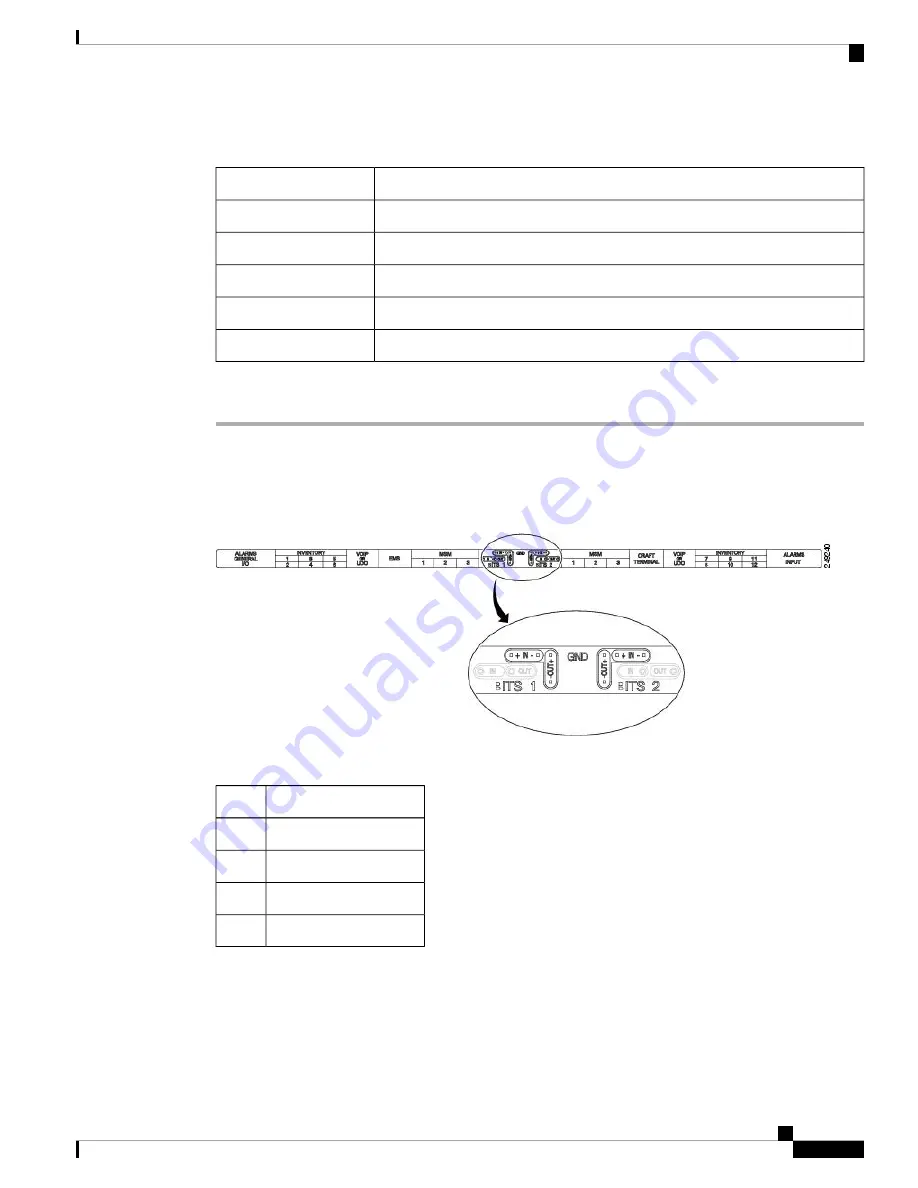
Locate the timing connector on the ECU module (BITS-1 or BITS-2 In/Out). The following figure shows
ECU module ANSI wire-wrap pins.
Table 38: ECU module Pin Assignments - ANSI, on page 403
lists the
ECU module pin assignments for ANSI.
Figure 272: ECU module ANSI Wire-wrap Pins
Table 38: ECU module Pin Assignments - ANSI
Function
Pin
Input from external drive
IN 1
Output to external drive
OUT 1
Input from external drive
IN 2
Output to external drive
OUT 2
Step 2
Connect one end of the wire-wrap clock cable to the corresponding wire-wrap connector on the ECU module,
and the other end to the external source of the timing. Change the timing input to high-impedance (lesser or
greater than 3 ohms) using a jumper on the ECU module. Remove the P1 jumper of the BITS-1 to change the
top timing input, and the P2 Jumper of the BITS-2 to change the bottom timing input.
Cisco ONS 15454 Hardware Installation Guide
403
Installing the ONS 15454 M6 Shelf
DLP-G296 Install Timing Wires on ONS 15454 M6 - ANSI
Summary of Contents for ONS 15454
Page 2: ... 2019 Cisco Systems Inc All rights reserved ...
Page 16: ...Cisco ONS 15454 Hardware Installation Guide xvi Contents ...
Page 28: ...Cisco ONS 15454 Hardware Installation Guide xxviii Preface Preface ...
Page 36: ...Cisco ONS 15454 Hardware Installation Guide 6 Overview Cisco ONS 15454 M6 Shelf ...
Page 510: ...Cisco ONS 15454 Hardware Installation Guide 480 Hardware Specifications Dimensions ...


