


16-76
Cisco ONS 15454 DWDM Installation and Operations Guide, R6.0
April 2006
Chapter 16 Card Reference
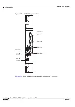
16.7.6 32WSS Card
16.7.5.2 AD-4B-xx.x Card-Level Indicators
The AD-4B-xx.x card has three card-level LED indicators, described in
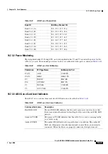
16.7.5.3 AD-4B-xx.x Port-Level Indicators
You can find the status of the card port using the LCD screen on the ONS 15454 fan-tray assembly. Use
the LCD to view the status of any port or card slot; the screen displays the number and severity of alarms
for a given port or slot. The AD-4B-xx.x has 12 LC-PC-II optical ports: eight for add/drop band client
input and output, two for express channel input and output, and two for communication.
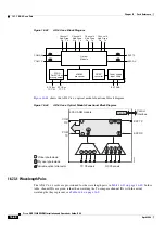
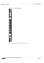
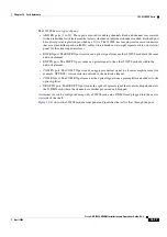
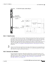
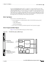
16.7.6 32WSS Card
The 32-Channel Wavelength Selective Switch (32WSS) card performs channel add/drop processing
within the ONS 15454 DWDM node. The 32WSS works in conjunction with the 32DMX to implement
ROADM functionality. Equipped with ROADM functionality, the ONS 15454 DWDM can be configured
to add or drop individual optical channels using CTC, Cisco MetroPlanner, and CTM.
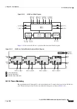
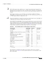
An ROADM network element utilizes two 32WSS cards (two slots each) and two 32DMX cards (one
slot each), for a total of six slots in the chassis. For a diagram of a typical ROADM configuration, see
the
“17.1.4 ROADM Node” section on page 17-8
. The 32WSS card can be installed in Slots 1 and 2, 3
and 4, 5 and 6, 12 and 13, 14 and 15, or 16 and 17.
Table 16-46
AD-4B-xx.x Port Calibration
Photodiode
CTC Type Name
Calibrated to Port
P1–P4
ADD
COM TX
P5–P8
DROP
DROP TX
P9
IN EXP
EXP RX
P10
OUT EXP
EXP TX
P11
IN COM
COM RX
V1
OUT COM
COM TX
Table 16-47
AD-4B-xx.x Card-Level Indicators
Card-Level Indicators
Description
Red FAIL LED
The red FAIL LED indicates that the card’s processor is not ready or that
there is an internal hardware failure. Replace the card if the red FAIL LED
persists.
Green ACT LED
The green ACT LED indicates that the AD-4B-xx.x card is carrying traffic
or is traffic-ready.
Amber SF LED
The amber SF LED indicates a signal failure. The amber SF LED also
illuminates when the transmit and receive fibers are incorrectly connected.
When the fibers are properly connected, the light turns off.
Summary of Contents for ONS 15454 DWDM
Page 38: ...Figures xxxviii Cisco ONS 15454 DWDM Installation and Operations Guide R6 0 August 2005 ...
Page 54: ...Procedures liv Cisco ONS 15454 DWDM Installation and Operations Guide R6 0 August 2005 ...
Page 64: ... 64 Cisco ONS 15454 DWDM Installation and Operations Guide R6 0 August 2005 Chapter ...


