


15-32
Cisco ONS 15454 DWDM Installation and Operations Guide, R6.0
September 2005
Chapter 15 Shelf Hardware Reference
15.9 ONS 15454 ANSI Alarm Expansion Panel
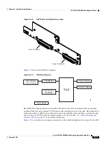
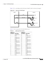
Figure 15-31
AEP Wire-Wrap Connections to Backplane Pins
shows the backplane pin assignments and corresponding signals on the AIC-I and AEP.
1
2
3
4
A
FG4
FG3
FG2
FG1
BITS
LAN
1
2
3
4
A
B
1
2
3
4
A
B
IN
1
2
3
4
A
B
IN/OUT
FG6
FG5
7
8
9
5
10
6
A
B
A
B
ENVIRONMENTAL ALARMS
IN
ACO
FG7
1
2
3
4
IN
A
B
FG8
1
2
3
4
A
B
MODEM
FG9
1
2
3
4
A
CRAFT
AUD
VIS
FG10
1
2
3
4
A
B
LOCAL ALARMS
IN
FG12
FG11
11
12
A
B
B
96618
White
Black
Blue
Green
Slate
Violet
Orange
Yellow
Red
Brown
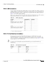
Table 15-6
Pin Assignments for the AEP
AEP Cable Wire
Backplane Pin
AIC-I Signal
AEP Signal
Black
A1
GND
AEP_GND
White
A2
AE_+5
AEP_+5
Slate
A3
VBAT–
VBAT–
Violet
A4
VB+
VB+
Blue
A5
AE_CLK_P
AE_CLK_P
Green
A6
AE_CLK_N
AE_CLK_N
Yellow
A7
AE_DIN_P
AE_DOUT_P
Orange
A8
AE_DIN_N
AE_DOUT_N
Red
A9
AE_DOUT_P
AE_DIN_P
Brown
A10
AE_DOUT_N
AE_DIN_N
Summary of Contents for ONS 15454 DWDM
Page 38: ...Figures xxxviii Cisco ONS 15454 DWDM Installation and Operations Guide R6 0 August 2005 ...
Page 54: ...Procedures liv Cisco ONS 15454 DWDM Installation and Operations Guide R6 0 August 2005 ...
Page 64: ... 64 Cisco ONS 15454 DWDM Installation and Operations Guide R6 0 August 2005 Chapter ...


