


4-25
Cisco ONS 15454 DWDM Installation and Operations Guide, R6.0
September 2005
Chapter 4 Perform Node Acceptance Tests
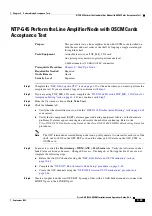
NTP-G45 Perform the Line Amplifier Node with OSCM Cards Acceptance Test
Step 14
Complete the
“DLP-G79 Verify the OPT-BST Amplifier Laser and Power” task on page 4-40
for the
east OPT-BST amplifier.
Step 15
Disconnect the TXP or tunable laser from the east OPT-BST card.
Step 16
Remove the loopback on the west OPT-BST created in
Step 17
Create a loopback on the east OPT-BST by connecting a patchcord from the LINE TX port to the LINE
RX port with a 10-dB bulk attenuator.
Step 18
If you are using a tunable laser, follow the manufacturer’s instructions to complete the following steps.
If you are using a TXP_MR_2.5G card, continue with
a.
Set the output power to a nominal value, such as –3 dBm.
b.
Set the tuner to the wavelength under test, then continue with
.
Step 19
If you are using a TXP_MR_2.5G card, complete the
“DLP-G268 Provision TXP_MR_2.5G Cards for
Acceptance Testing” task on page 4-4
for the TXP containing the wavelength you will test. Refer to
, if needed.
Step 20
Connect the tunable laser transmitter or the TXP_MR_2.5G card DWDM TX port to the LINE RX port
of the west OPT-BST using a 10-dB bulk attenuator.
Caution
Failure to use proper attenuation might damage equipment.
Step 21
Wait 90 seconds, then in node view click the
Alarms
tab. Verify that the LOS alarms on the east
OPT-BST and OSCM cards have cleared. The clearing of the LOS alarms indicates that the OSC link is
active on the east side.
Note
An SDCC Termination Failure alarm will continue to appear due to the OSC signal loopback.
An LOS-O alarm appears on the west OPT-BST card, and an LOS alarm appears on the west
OCSM card.
If the alarms clear, continue with
. If not, perform the following steps:
a.
Display the east OPT-BST card in card view.
b.
Click the
Provisioning > Optical Line > Optics Thresholds
tabs.
c.
Under Types, click
Alarms
, then click
Refresh
.
d.
Locate the Port 2 Power Failure Low parameter. Double-click the table cell and change the value to
–30 dBm.
e.
Locate the Port 4 Power Failure Low parameter. Double-click the table cell and change the value to
–40 dBm.
f.
Click
Apply
, and then
Yes
.
g.
Wait 90 seconds, then in node view click the
Alarms
tab. Verify that the LOS alarms on the east
OPT-BST card has cleared. If so, continue with
. If not, disconnect the OSCM card from the
OPT-BST.
h.
Create a loopback on the OSCM card by connecting a patch cable from the OSC TX port to the OSC
RX port using a 10-dB bulk attenuator.
i.
Wait 90 seconds, then in node view click the
Alarms
tab. Verify that the LOS alarms on the east
OSCM card has cleared. If so, replace the OPT-BST card. If not, replace the OSCM card. See
the
“NTP-G30 Install the DWDM Cards” procedure on page 3-39
.
Summary of Contents for ONS 15454 DWDM
Page 38: ...Figures xxxviii Cisco ONS 15454 DWDM Installation and Operations Guide R6 0 August 2005 ...
Page 54: ...Procedures liv Cisco ONS 15454 DWDM Installation and Operations Guide R6 0 August 2005 ...
Page 64: ... 64 Cisco ONS 15454 DWDM Installation and Operations Guide R6 0 August 2005 Chapter ...


