background image


1-27

Cisco ONS 15454 DWDM Procedure Guide, R8.0

78-17704-02

Chapter 1 Install the Shelf and Common Control Cards

NTP- G12 Remove the FMEC Cover

DLP-G12 Remove the FMEC Cover 

Step 1

Unscrew the nut holding the ground wire to the shelf. Remove the nut and washer. 

Step 2

Remove the ground wire from the left side of the shelf. 

Step 3

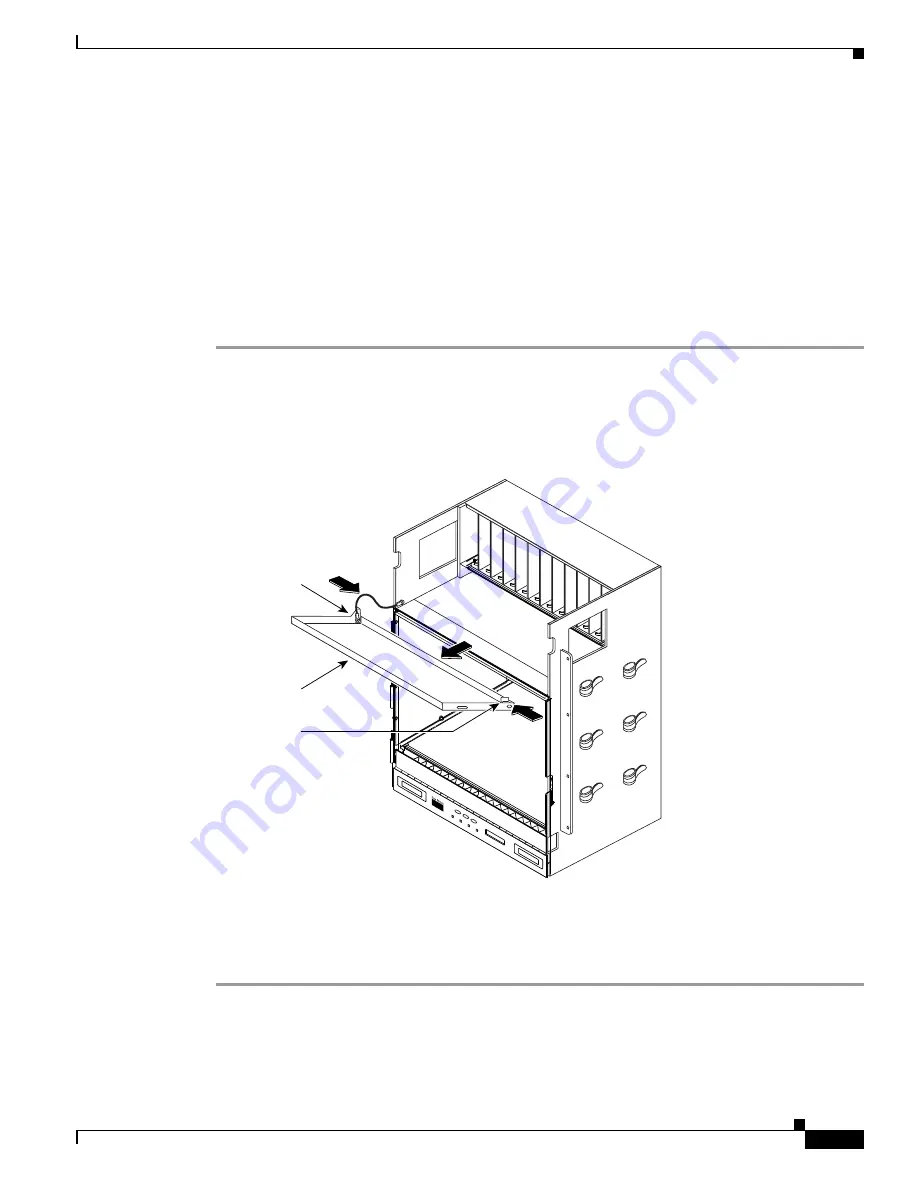
Pull the right side of the hinge-locking spring (

Figure 1-13

).

Figure 1-13

Removing the ONS 15454 FMEC Cover 

Step 4

Detach the cover from the pin of the hinge.

Step 5

Remove the cover carefully from the left pin of the hinge.

Step 6

Return to your originating procedure (NTP).

Purpose

This task removes the FMEC cover in order to install the MIC-A/P and the 
MIC-C/T/P.

Tools/Equipment

Medium slot-head screwdriver 

Prerequisite Procedures

DLP-G11 Open the FMEC Cover, page 1-26


Required/As Needed

As needed

Onsite/Remote

Onsite

Security Level

None

71087

FAN

 FAIL

CRIT

MAJ

MIN

Pin hinge

FMEC cover

Hinge-locking

spring

Summary of Contents for ONS 15454 ANSI

Page 1: ...sembly procedure on page 1 8 2 NTP G2 Install the Shelf Assembly page 1 8 Complete this procedure to install the shelf assembly in a rack 3 NTP G3 Open and Remove the Front Door page 1 21 Complete this procedure to access the equipment before continuing with other procedures in this chapter 4 NTP G4 Open and Remove the FMEC Cover ETSI Only page 1 25 Complete this procedure to access the electrical...

Page 2: ...1 Complete this procedure as needed 17 NTP G158 Connect a Multishelf Node and Subtending Shelves to a Catalyst 2950 page 1 83 Complete this procedure as needed 18 NTP G159 Configure a Cisco Catalyst 2950 for a Multishelf Node page 1 83 Complete this procedure as needed 19 NTP G16 Perform the Shelf Installation Acceptance Test page 1 85 Complete this procedure to determine if you have correctly com...

Page 3: ...ools and equipment to install and test the ONS 15454 ANSI shelf assembly Cisco Supplied Materials ANSI The following materials are required and are shipped with the ONS 15454 ANSI shelf wrapped in plastic The number in parentheses gives the quantity of the item included in the package 12 24 x 3 4 pan head Phillips mounting screws 48 1004 XX 48 1007 XX 8 12 24 x 3 4 socket set screws 48 1003 XX 2 T...

Page 4: ...s with UPC polish 55 dB or better for optical OC N cards Shielded coaxial cable terminated with SMB or BNC connectors for DS 3 cards Shielded ABAM cable terminated with AMP Champ connectors or unterminated for DS1N 14 cards with 22 or 24 AWG 0 51 mm or 0 64 mm ground wire typically about two ft 61 cm in length 6 pair 29 AWG double shielded cable Tie wraps and or lacing cord Labels CLETOP cleaning ...

Page 5: ... front door 1 Hex key 3 mm long arm 1 Bottom brackets for the fan tray air filter Cable assembly Ethernet RJ 45 1 Power cable from fuse and alarm panel to MIC A P and MIC C T P 2 Caution Only use the power cables that are designed to be used with ONS 15454 ETSI They are sold separately User Supplied Equipment ETSI The following materials and tools are required for installation but are not supplied...

Page 6: ...nding cable into the lug Wire stripping tool Test Equipment ETSI To install the ONS 15454 ETSI you need the following test equipment Voltmeter Power meter only for use with fiber optics BER tester for E1 N 14 E1 42 E3 12 DS3i N 12 STM1E 12 and FMEC cards NTP G1 Unpack and Inspect the Shelf Assembly Step 1 Complete the DLP G1 Unpack and Verify the Shelf Assembly task on page 1 7 Step 2 Complete the...

Page 7: ...uipment ANSI section on page 1 3 Note The fan tray assembly is shipped separately Step 5 Return to your originating procedure NTP DLP G2 Inspect the Shelf Assembly Step 1 Open the shelf using the pinned hex key For more information see the DLP G9 Open the Front Cabinet Compartment Door task on page 1 22 Step 2 Verify the following The pins are not bent or broken The frame is not bent Step 3 If the...

Page 8: ...g must not exceed 30A Statement 1045 Warning To prevent the system from overheating do not operate it in an area that exceeds the maximum recommended ambient temperature of 45 degrees C 113 degrees F Statement 1047 Warning Take care when connecting units to the supply circuit so that wiring is not overloaded Statement 1018 Purpose This procedure reverses the mounting bracket and mounts shelf assem...

Page 9: ...nch 584 2 mm to a 19 inch 482 6 mm rack Step 2 ANSI shelves only To install the air filter on the bottom of the shelf rather than below the fan tray assembly complete the DLP G4 Install the External Brackets and Air Filter ANSI Only task on page 1 11 Step 3 Complete the necessary rack mount task as applicable DLP G5 Mount the Shelf Assembly in a Rack One Person page 1 13 DLP G6 Mount the Shelf Ass...

Page 10: ...assembly Step 2 Flip the detached mounting bracket upside down Text imprinted on the mounting bracket will now also be upside down Step 3 Place the widest side of the mounting bracket flush against the shelf assembly see Figure 1 1 The narrow side of the mounting bracket should be towards the front of the shelf assembly Text imprinted on the mounting bracket should be visible and upside down Step ...

Page 11: ...15454 CC FTA Purpose This task installs the external brackets and air filter on the bottom of the shelf rather than below the fan tray assembly Installing the external brackets and air filter on the bottom of the shelf enables access to the air filter without removing the fan tray assembly This task applies to the ONS 15454 ANSI shelf only Tools Equipment 2 Phillips Dynamometric screwdriver Medium...

Page 12: ...eft and right sides of the bottom of the shelf assembly Step 3 Secure each bracket to the bottom of the shelf assembly using the screws 48 0003 provided in the backplane standoff kit 53 0795 XX Each bracket has a filter stopper and a flange on one end Make sure to attach the brackets with the stoppers and flanges facing the rear of the shelf assembly the top if the ONS 15454 is facedown during ins...

Page 13: ...ly unit in the rack Step 1 Verify that the proper fuse and alarm panel has been installed in the top mounting space If a fuse and alarm panel is not present you must install one according to manufacturer instructions The fuse rating for both ETSI and ANSI chassis must not exceed 30A Step 2 Ensure that the shelf assembly is set for the desired rack size either 23 inches 584 2 mm or 19 inches 482 6 ...

Page 14: ...iently to hold the mounting brackets Step 4 Lift the shelf assembly to the desired position in the rack and set it on the screws Step 5 Align the screw holes on the mounting brackets with the mounting holes in the rack Step 6 Using the Phillips Dynamometric screwdriver install one mounting screw in each side of the assembly Step 7 When the shelf assembly is secured to the rack install the remainin...

Page 15: ...e ONS 15454 Step 1 Verify that the proper fuse and alarm panel has been installed in the top mounting space If a fuse and alarm panel is not present you must install one according to manufacturer s instructions The fuse rating for both ETSI and ANSI chassis must not exceed 30A Step 2 Ensure that the shelf assembly is set for the desired rack size either 23 inches 584 2 mm or 19 inches 482 6 mm Ste...

Page 16: ...o allow air flow to the fan intake If a second ONS 15454 ETSI is installed above a shelf assembly the air ramp between the shelves provides space for air flow When using third party equipment above the ONS 15454 ETSI provide a minimum of 25 mm 1 inch between the third party unit and the bottom of the ONS 15454 ETSI The third party equipment must not vent heat upward into the ONS 15454 ETSI Note Th...

Page 17: ... Mount the first shelf assembly in the bottom of the rack using the DLP G5 Mount the Shelf Assembly in a Rack One Person task on page 1 13 or the DLP G6 Mount the Shelf Assembly in a Rack Two People task on page 1 15 Figure 1 4 shows a three shelf ONS 15454 ETSI bay assembly Figure 1 4 Three Shelf ONS 15454 ETSI ONS 15454 SDH Bay Assembly Step 3 ETSI only Mount the air ramp above the ONS 15454 ETS...

Page 18: ... or 23 inch 584 2 mm rack Locate the rack mount unit RMU space specified in your site plan Refer to the Shelf Assembly Hardware chapter in the Cisco ONS 15454 DWDM Reference Manual for more information about air ramp placement Step 2 Verify the rack type of your air ramp installation The brackets are compatible with the following racks 19 inch racks as defined in IEC 297 1 2 Nos 19 inch for deep d...

Page 19: ...holes insert and tighten the four screws In an ETSI configuration the air ramp comes with pre installed brackets as illustrated in Figure 1 6 Figure 1 6 Air Ramp with Brackets in an ETSI Configuration Step 5 To install the 19 inch and 23 inch brackets on an ONS 15454 ANSI with standard door and spool remove the screws that attach the mounting bracket to the side of the shelf assembly Step 6 Align ...

Page 20: ...the 19 inch and 23 inch brackets in an ONS 15454 ANSI deep door remove the screws that attach the mounting bracket to the side of the shelf assembly Step 9 Align the mounting bracket screw holes against the shelf assembly screw holes according to Figure 1 8 Step 10 The bracket mounting holes will align with the forward most mounting holes on the air ramp When aligned properly the mounting flange w...

Page 21: ...ete the DLP G10 Remove the Front Door task on page 1 23 Step 3 If you are using an ETSI shelf continue with the NTP G4 Open and Remove the FMEC Cover ETSI Only procedure on page 1 25 If you are using an ANSI shelf continue with the NTP G5 Remove the Backplane Covers ANSI Only procedure on page 1 28 Purpose This procedure opens and removes the front door to access the equipment Tools Equipment Open...

Page 22: ...ht side It is labeled ESD on the top and bottom Always wear an ESD wrist strap and connect the strap to the ESD plug when working on the ONS 15454 Step 1 Open the front door lock The ONS 15454 shelf assembly comes with a pinned hex key for locking and unlocking the front door Turn the key counterclockwise to unlock the door and clockwise to lock it Figure 1 9 illustrates the front door of the ANSI...

Page 23: ...rn to your originating procedure NTP DLP G10 Remove the Front Door Step 1 For ONS 15454 ETSI shelves a Unscrew the nut holding the ground wire to the shelf Remove the nut and washer Purpose This task removes the front cabinet compartment door Tools Equipment Open end wrench Prerequisite Procedures DLP G9 Open the Front Cabinet Compartment Door page 1 22 Required As Needed As needed Onsite Remote O...

Page 24: ...lowing To detach the ground strap from the front door loosen the 6 Kepnut 49 0600 01 using the open end wrench Detach the end of the ground strap terminal lug 72 3622 01 from the male stud on the inside of the door To detach the other end of the ground strap from the longer screw on the fiber guide loosen the 4 Kepnut 49 0337 01 on the terminal lug using the open end wrench Remove the terminal lug...

Page 25: ...move the FMEC Cover task on page 1 27 Step 3 Continue with the NTP G6 Install the MIC A P and MIC T C P FMECs ETSI Only procedure on page 1 30 Purpose This procedure opens and removes the FMEC cover on the ONS 15454 ETSI The ONS 15454 ETSI has a screw in panel over the EFCA The FMEC cover protects the FMEC cards Tools Equipment Medium slot head screwdriver Prerequisite Procedures NTP G2 Install th...

Page 26: ...e FMEC Cover Step 2 Use the handles to pull the cover forward Step 3 Return to your originating procedure NTP Purpose This task opens the FMEC cover The FMEC cover must be opened to install the MIC A P and the MIC C T P Tools Equipment Medium slot head screwdriver Prerequisite Procedures DLP G9 Open the Front Cabinet Compartment Door page 1 22 Required As Needed Required Onsite Remote Onsite Secur...

Page 27: ...g spring Figure 1 13 Figure 1 13 Removing the ONS 15454 FMEC Cover Step 4 Detach the cover from the pin of the hinge Step 5 Remove the cover carefully from the left pin of the hinge Step 6 Return to your originating procedure NTP Purpose This task removes the FMEC cover in order to install the MIC A P and the MIC C T P Tools Equipment Medium slot head screwdriver Prerequisite Procedures DLP G11 Op...

Page 28: ...Figure 1 14 Purpose This procedure describes how to access the ONS 15454 ANSI backplane by removing the covers The backplane has two sheet metal covers one on either side and a lower backplane cover at the bottom Tools Equipment 2 Phillips Dynamometric screwdriver Medium slot head screwdriver Small slot head screwdriver Prerequisite Procedures NTP G2 Install the Shelf Assembly page 1 8 NTP G3 Open...

Page 29: ...Step 2 Loosen the nine perimeter screws that hold the backplane sheet metal cover s in place Step 3 Lift the panel by the bottom to remove it from the shelf assembly Step 4 Store the panel for later use Attach the backplane cover s whenever electrical interface assemblies EIAs are not installed Step 5 Return to your originating procedure NTP Purpose This task removes the backplane sheet metal cove...

Page 30: ...vides connection for eight alarm outputs coming from the TCC2 TCC2P card sixteen alarm inputs and four configurable alarm inputs outputs FMEC Slot 24 supports the MIC C T P The MIC C T P card provides connection for the BATTERY A input one of the two possible redundant power supply inputs It also provides connection for system management serial port system management LAN port and system timing inp...

Page 31: ... NTP G6 Install the MIC A P and MIC T C P FMECs ETSI Only Figure 1 15 Installing FMECs on the ONS 15454 ETSI Step 5 Tighten the screws Step 6 Continue with the NTP G7 Install the Power and Ground procedure on page 1 32 Stop You have completed this procedure 61338 FAN FAIL CR IT MAJ MIN Mounting screws Guide rail ...

Page 32: ...r Medium slot head screwdriver Small slot head screwdriver Screws Ground cable 13 3 mm 6 AWG stranded Listed pressure terminal connectors such as ring and fork types connectors must be suitable for 10 AWG copper conductors Wire cutters Wire strippers Crimp tool Fuse panel ANSI only Power cable from fuse and alarm panel to assembly 10 AWG copper conductors 194 degrees F 90 degrees C Wire wrapper ET...

Page 33: ... removed to de energize the unit Statement 1028 Caution Always use the supplied ESD wristband when working with a powered ONS 15454 Plug the wristband cable into the ESD jack located on the lower right outside edge of the shelf assembly Step 1 Verify that the correct fuse and alarm panel is installed in the top mounting space The fuse rating for both ETSI and ANSI chassis must not exceed 30 A Step...

Page 34: ... lug against the grounding receptacle on the side panel of the shelf Step 6 Insert one of the screws through the locking washer and through the hole in the grounding lug Insert the screw into the threaded holes on the right side of the shelf Ensure that the grounding lug does not interfere with other system hardware or rack equipment Step 7 Repeat Step 6 with the second screw Step 8 Prepare the ot...

Page 35: ...454 ANSI shelf Tools Equipment 2 Phillips Dynamometric screwdriver Medium slot head screwdriver Small slot head screwdriver Screws Power cable from fuse and alarm panel to assembly 10 AWG copper conductors 194 degrees F 90 degrees C Ground cable 6 AWG stranded Listed pressure terminal connectors such as ring and fork types connectors must be suitable for 10 AWG copper conductors Prerequisite Proce...

Page 36: ... backplane Note When terminating a frame ground use the Kepnut provided with the ONS 15454 and tighten it to a torque specification of 31 in lb The Kepnut provides a frame ground connection that minimizes the possibility of loosening caused by rotation during installation and maintenance activity The type of prevention the Kepnut provides for the frame ground connection is inherently provided by t...

Page 37: ... and ground conductors Connectors must be suitable for copper conductors Caution When terminating power return and frame ground do not use soldering lug connectors screwless push in connectors quick connect connectors or other friction fit connectors Purpose This task connects power to the ONS 15454 ETSI shelf Tools Equipment 2 Phillips Dynamometric screwdriver Medium slot head screwdriver Small s...

Page 38: ...able to the fuse panel or power source Use the pin connections in Table 1 1 Step 5 Return to your originating procedure NTP DLP G18 Connect Office Power to the ONS 15454 ANSI Table 1 1 Pin Connection of the Power FMECs Pin Function Cable Color A1 Battery return Black A2 48 V battery Red A3 Ground Green with yellow stripes Purpose This task connects power to the ONS 15454 ANSI shelf Tools Equipment...

Page 39: ...e on page 3 10 If you are using the TCC2 TCC2P cards the system clock will run for up to three hours In this case no action would be required Step 1 Connect the office power according to the fuse panel engineering specifications Step 2 Measure and cut the cables as needed to reach the ONS 15454 from the fuse panel Figure 1 18 shows the ONS 15454 power terminals Step 3 Dress the power according to ...

Page 40: ...gure 1 18 follow a torque specification of 10 in lb Step 7 Terminate the return 1 lead to the RET1 backplane terminal Use oxidation prevention grease to keep the connections noncorrosive Step 8 Terminate the negative 1 lead to the negative BAT1 backplane power terminal Use oxidation prevention grease to keep connections noncorrosive Step 9 If you use redundant power leads terminate the return 2 le...

Page 41: ... present The voltmeter must read 0 VDC Step 2 Insert the fuse into the fuse position according to site practice The fuse rating must not exceed 30A Step 3 At the bottom rear of the shelf assembly remove the cover panel to access the power connections Step 4 Using a voltmeter verify the ONS 15454 shelf for 48 VDC battery and ground a To verify the A side of the shelf place the black lead of the vol...

Page 42: ...ult in damage to the filter the fan tray or both Caution Do not force a fan tray assembly into place This can damage the connectors on the fan tray and or the connectors on the back panel of the shelf assembly Note 15454 CC FTA is compatible with Software Release 2 2 2 and greater and shelf assemblies 15454 SA HD and 15454 SA ANSI 15454E CC FTA is compatible with Software Release 4 0 and greater a...

Page 43: ...ution Although the air filter can work with older fan trays if it is installed with either side facing up Cisco recommends that you install it with the metal bracing facing up to preserve the surface of the filter You must install the air filter with the metal bracing facing up with 15454E CC FTA or 15454 CC FTA Step 2 Install the fan tray assembly Figure 1 19 shows the fan tray assembly location ...

Page 44: ...ure Guide R8 0 78 17704 02 Chapter 1 Install the Shelf and Common Control Cards NTP G8 Install the Fan Tray Assembly Figure 1 19 Installing the Fan Tray Assembly on the ONS 15454 ETSI 61236 FAN FAIL CR IT MAJ MIN Fan tray assembly LCD ...

Page 45: ...ugged into the assembly look at the fan tray and listen to determine that the fans are running Step 4 If you want to install an alarm expansion panel on the ONS 15454 ANSI shelf continue with the NTP G9 Install the Alarm Expansion Panel ANSI Only procedure on page 1 46 Otherwise continue with the NTP G10 Attach Wires to Alarm Timing LAN and Craft Pin Connections procedure on page 1 49 Stop You hav...

Page 46: ... with standoffs Insert the longer standoff on the left and the shorter standoff on the right Figure 1 21 Purpose This procedure installs an AEP onto the 15454 SA ANSI or 15454 SA HD shelf backplane The AEP provides alarm contacts 32 inputs 16 outputs in addition to the 16 provided by the AIC I card Typically the AEP is preinstalled when ordered with the ONS 15454 ANSI however the AEP can be ordere...

Page 47: ...lf and Common Control Cards NTP G9 Install the Alarm Expansion Panel ANSI Only Figure 1 21 Replace Backplane Screws with Standoffs Step 2 Attach the remaining two standoffs on either side of the backplane Figure 1 22 Step 3 Position the AEP board over the standoffs 78402 Longer Shorter ...

Page 48: ...three screws to secure the AEP to the backplane Step 5 Connect the AEP cable to the backplane and AEP a Connect the 10 colored wires to the wire wrap pins on the backplane Figure 1 23 shows where the cable wires are connected Table 1 2 shows AEP and AIC I signals that each wire carries b Plug the other end of the AEP cable into AEP connector port Figure 1 23 AEP Wire Wrap Connections to Backplane ...

Page 49: ...D AEP_GND White A2 AE_ 5 AEP_ 5 Slate A3 VBAT VBAT Violet A4 VB VB Blue A5 AE_CLK_P AE_CLK_P Green A6 AE_CLK_N AE_CLK_N Yellow A7 AE_DIN_P AE_DOUT_P Orange A8 AE_DIN_N AE_DOUT_N Red A9 AE_DOUT_P AE_DIN_P Brown A10 AE_DOUT_N AE_DIN_N Purpose This procedure installs alarm timing LAN and craft wires on the ONS 15454 shelf These wires are attached to the mechanical interface card MIC FMECs on the ETSI...

Page 50: ...plane ANSI Only task on page 1 57 if you are provisioning external timing Complete the DLP G25 Install LAN Wires on the Backplane ANSI Only task on page 1 58 to create an external LAN connection You must either install LAN wires on the backplane or connect a CAT 5 Ethernet cable to the LAN port on the TCC2 TCC2P card to create an external LAN connection Complete the DLP G26 Install the TL1 Craft I...

Page 51: ... number 3 9 ALMINP3 Alarm input pair number 4 10 ALMINP3 Alarm input pair number 4 11 EXALM0 Extra alarm 0 12 EXALM0 Extra alarm 0 13 FGND Ground 14 EXALM1 Extra alarm 1 15 EXALM1 Extra alarm 1 16 EXALM2 Extra alarm 2 17 EXALM2 Extra alarm 2 18 EXALM3 Extra alarm 3 19 EXALM3 Extra alarm 3 20 EXALM4 Extra alarm 4 21 EXALM4 Extra alarm 4 22 EXALM5 Extra alarm 5 23 EXALM5 Extra alarm 5 24 EXALM6 Extr...

Page 52: ...ut pair number 3 44 ALMOUP3 Normally open output pair number 4 45 ALMOUP3 Normally open output pair number 4 46 AUDALM0 Normally open minor audible alarm 47 AUDALM0 Normally open minor audible alarm 48 AUDALM1 Normally open major audible alarm 49 AUDALM1 Normally open major audible alarm 50 AUDALM2 Normally open critical audible alarm 51 AUDALM2 Normally open critical audible alarm 52 FGND Ground ...

Page 53: ...o 100 120 ohms Table 1 4 shows MIC C T P pin assignments A high impedance option 3 kilo ohms or greater is possible through a jumper on the MIC C T P FMEC You can change the top timing input to high impedance by removing the jumper on P3 of the MIC C T P FMEC You can change the bottom timing input to high impedance by removing the jumper on P2 on the MIC C T P FMEC Note Refer to ITU T G 813 for ru...

Page 54: ...computer connected directly to the TCC2 TCC2P card is not connected to the same LAN Step 1 Using 0 51 mm or 0 64 mm 22 or 24 AWG wire or CAT 5 Ethernet cable connect the wires to the RJ 45 connector according to Table 1 5 Purpose This task installs the LAN wires on the ONS 15454 ETSI MIC C T P Tools Equipment Standard CAT 5 Ethernet cable straight through for data terminating equipment DTE or cros...

Page 55: ...n the Release 3 4 or higher ONS 15454 backplane and Figure 1 25 calls out the external alarm pins on that backplane LAN 1 Connecting to DTE a PC workstation or router Straight through Ethernet cable 1 1 PNMSRX white green 2 2 PNMSRX green 3 3 PNMSTX white orange 4 4 5 5 6 6 PNMSTX orange 7 7 8 8 1 The Cisco ONS 15454 ETSI is DCE Purpose This task installs alarm wires on the backplane so that you c...

Page 56: ...mber 2 Critical audible alarm B2 A3 Alarm output pair number 3 Major audible alarm A1 B3 B1 A4 Alarm output pair number 4 Minor audible alarm A2 B4 B2 LOCAL ALARMS VIS Visual A1 Alarm output pair number 1 Remote visual alarm A3 B1 A2 Alarm output pair number 2 Critical visual alarm B2 A3 Alarm output pair number 3 Major visual alarm B3 A4 Alarm output pair number 4 Minor visual alarm B4 A1 A2 B3 A...

Page 57: ...ng wires on the ONS 15454 ANSI backplane Tools Equipment Wire wrapper 100 ohm shielded BITS clock cable pair 22 or 24 AWG 0 51 mm or 0 64 mm twisted pair T1 type Prerequisite Procedures NTP G5 Remove the Backplane Covers ANSI Only page 1 28 Required As Needed As needed Onsite Remote Onsite Security Level None 1 2 3 4 A FG4 FG3 FG2 FG1 BITS LAN 1 2 3 4 A B 1 2 3 4 A B IN 1 2 3 4 A B IN OUT FG6 FG5 ...

Page 58: ...ctly to the TCC2 TCC2P is not connected to the same LAN Step 1 Using 22 or 24 AWG 0 51 mm or 0 64 mm wire or CAT 5 Ethernet cable wrap the wires on the appropriate wire wrap pins according to local site practice Caution Cross talk might result if both receive Rx and transmit Tx pins connect on the same twisted pair of wires from the CAT 5 cable The two Tx pins need to be on one twisted pair and th...

Page 59: ...riate wire wrap pins according to local site practice Step 2 Wrap the ground shield of the craft interface cable to the frame ground pin Wrap the ground wire of your computer cable to pin A3 on the craft pin field Table 1 8 shows the pin assignments for the CRAFT pin field Note You cannot use the craft backplane pins and the EIA TIA 232 port on the TCC2 TCC2P card simultaneously Using a combinatio...

Page 60: ...re that the AEP AMP Champ connectors protrude through the cutouts in the lower cover Figure 1 26 Table 1 8 Craft Interface Pin Assignments Pin Field Contact Function Craft A1 Receive A2 Transmit A3 Ground A4 DTR Purpose This procedure connects an external wire wrap panel to the ONS 15454 ANSI AEP to provide the physical alarm contacts for the AEP Tools Equipment External wire wrap panel Prerequisi...

Page 61: ...t the cables from the external wire wrap panel to the AMP Champ connectors on the AEP Table 1 9 lists the alarm input pin assignments Table 1 9 Alarm Input Pin Assignments AMP Champ Pin Signal Name AMP Champ Pin Signal Name 1 ALARM_IN_1 27 GND 2 GND 28 ALARM_IN_2 3 ALARM_IN_3 29 ALARM_IN_4 4 ALARM_IN_5 30 GND 5 GND 31 ALARM_IN_6 6 ALARM_IN_7 32 ALARM_IN_8 7 ALARM_IN_9 33 GND 8 GND 34 ALARM_IN_10 9...

Page 62: ...24 19 ALARM_IN_25 45 GND 20 GND 46 ALARM_IN_26 21 ALARM_IN_27 47 ALARM_IN_28 22 ALARM_IN_29 48 GND 23 GND 49 ALARM_IN_30 24 ALARM_IN_31 50 25 ALARM_IN_ 51 GND1 26 ALARM_IN_0 52 GND2 Table 1 9 Alarm Input Pin Assignments continued AMP Champ Pin Signal Name AMP Champ Pin Signal Name Table 1 10 Alarm Output Pin Assignments AMP Champ Pin Signal Name AMP Champ Pin Signal Name 1 27 COM_0 2 COM_1 28 3 NO...

Page 63: ... 5 XREF 5 ALARM_IN_2 XREF 5 ALARM_IN_3 XREF 5 ALARM_IN_4 XREF 5 ALARM_IN_5 ALARM_IN_6 XREF 5 ALARM_IN_7 XREF 5 XREF 5 ALARM_IN_9 XREF 5 ALARM_IN_10 XREF 5 ALARM_IN_11 XREF 5 ALARM_IN_12 XREF 5 ALARM_IN_13 XREF 5 ALARM_IN_14 XREF 5 ALARM_IN_15 XREF 6 ALARM_IN_16 XREF 6 ALARM_IN_17 XREF 6 ALARM_IN_18 XREF 6 ALARM_IN_19 XREF 6 ALARM_IN_20 ALARM_IN_21 XREF 6 XREF 6 ALARM_IN_22 XREF 6 ALARM_IN_24 XREF ...

Page 64: ...10 XREF 7 NO_10 XREF 7 COM_8 XREF 7 NO_8 XREF 7 COM_6 XREF 7 NO_6 XREF 7 COM_4 XREF 7 NO_4 XREF 7 COM_2 XREF 7 NO_1 XREF 7 NO_2 XREF 7 COM_0 XREF 7 NO_0 XREF 7 NO_15 XREF 7 COM_15 XREF 7 NO_13 XREF 7 COM_13 XREF 7 COM_1 XREF 7 NO_11 XREF 7 COM_11 XREF 7 NO_9 XREF 7 COM_9 XREF 7 NO_7 XREF 7 COM_7 XREF 7 Connector Alarm Output GND1 GND2 1 10 11 12 13 14 15 16 17 18 19 2 20 21 22 23 24 25 26 27 28 29...

Page 65: ... 5 Attach the washer and nut Step 6 Attach the cover to the shelf using the screws on the top of the cover Step 7 Continue with the NTP G14 Install DWDM Equipment procedure on page 1 67 Stop You have completed this procedure NTP G13 Install the Rear Cover ANSI Only 71087 FAN FAIL CR IT MAJ MIN Pin hinge FMEC cover Hinge locking spring Purpose The following procedure explains how to install the rea...

Page 66: ...rews easy to locate Step 2 Loosen the top and bottom screws on one edge of the backplane to provide room to slide the mounting brackets into place using the U shaped screw slots on each end Step 3 Slide one of the mounting brackets into place and tighten the screws Step 4 Repeat Steps 2 and 3 for the second mounting bracket Step 5 Attach the cover by hanging it from the mounting screws on the back...

Page 67: ...Adapter Panel task on page 1 70 as needed Step 5 Complete the DLP G351 Install the Y Cable Module Tray task on page 1 71 as needed Step 6 Complete the DLP G30 Install the FlexLayer Shelf task on page 1 71 as needed 55374 R E T 1 C A U TI O N R em ov e po w er fro m bo th th e B A T1 an d te rm in al bl oc ks pr io r to se rv ic in g S U IT A B LE FO R M O U N TI N G O N A N O N C O M B U S TI B LE...

Page 68: ...able Module Tray task on page 1 74 as needed Stop You have completed this procedure DLP G27 Install the DCU Shelf Assembly Step 1 The DCU chassis requires 1 RU in a standard 19 inch 482 6 mm or 23 inch 584 2 mm rack Locate the RMU space specified in your site plan Refer to the Shelf Assembly Hardware chapter in the Cisco ONS 15454 DWDM Reference Manual for common site layout plans Step 2 Two sets ...

Page 69: ...tep 4 Connect a frame ground to the ground terminal provided on either side of the chassis Use minimum 14 AWG wire Step 5 Repeat Steps 2 through 4 for each patch panel tray you want to install Step 6 Return to your originating procedure NTP DLP G29 Install the Fiber Storage Tray Step 1 The fiber storage tray requires 1 RU in a standard 19 inch 482 6 mm or 23 inch 584 2 mm rack Locate the RMU space...

Page 70: ...ETSI site configurations Step 2 Verify that the mounting brackets attached to the unit are correct for your rack size Complete the DLP G3 Reverse the Mounting Bracket to Fit a 19 inch 482 6 mm Rack ANSI Only task on page 1 10 as required Step 3 Align the chassis with the rack mounting screw holes insert the four screws and tighten Caution Any paint between the EAP mounting ears and the frame of th...

Page 71: ...ayer shelf requires 1 RU in a standard 19 inch 482 6 mm or 23 inch 584 2 mm rack Locate the RMU space specified in your site plan Refer to the Shelf Assembly Hardware chapter in the Cisco ONS 15454 DWDM Reference Manual for typical DWDM site layout plans Step 2 A set of mounting brackets are included with the FlexLayer mounting kit one set each for 19 inch 482 6 mm or 23 inch 584 2 mm racks Verify...

Page 72: ...r shelf assembly You can only install two channel FlexLayer modules Tools Equipment 2 Phillips Dynamometric screwdriver FlexLayer modules Prerequisite Procedures None Required As Needed As needed Onsite Remote Onsite Security Level None Table 1 11 ONS 15xxx Two Channel Add Drop FlexLayer Module Hardware Part Numbers Part Number Description 15216 FLB 2 31 1 ITU 100 GHz 2 Ch FlexMod 1530 33 and 1531...

Page 73: ... NTP DLP G32 Install the Y Cable Protection Modules in the FlexLayer Shelf 15216 FLB 2 58 9 ITU 100 GHz 2 Ch FlexMod 1558 17 and 1558 98 15216 FLB 2 60 6 ITU 100 GHz 2 Ch FlexMod 1559 79 and 1560 61 Table 1 11 ONS 15xxx Two Channel Add Drop FlexLayer Module Hardware Part Numbers continued Part Number Description Purpose This task installs the Y cable protection modules in the FlexLayer shelf assem...

Page 74: ...he Y cable modules Step 2 Open the drawer of the tray by pushing inward on the latches located at the left and right front of the tray Step 3 In the tray pull up the latches on either side of the module frame and slide the frame upward until it is fully extended Step 4 Line up the first Y cable module that you want to install with the desired slot pull the latch at the bottom of the Y cable module...

Page 75: ...elf Statement 94 Caution Always use the supplied ESD wristband when working with a powered ONS 15454 Plug the wristband cable into the ESD jack located on the lower right outside to edge of the shelf assembly Note If protective clips are installed on the backplane connectors of the cards remove the clips before installing the cards Purpose This procedure describes how to install the common control...

Page 76: ...C2P during the software transfer process will corrupt the system memory Note Allow each card to boot completely before installing the next card Step 1 Open the latches ejectors of the first TCC2 TCC2P card that you will install Step 2 Use the latches ejectors to firmly slide the card along the guide rails until the card plugs into the receptacle at the back of the slot Slot 7 or 11 Note In Step 4 ...

Page 77: ...n green and the ACT STBY remains on The ACT STBY LED will be green if this is the first TCC2 card installed and amber if this is the second TCC2 card installed b For the TCC2P card All LEDs turn on briefly The red FAIL LED the yellow ACT STBY LED the green SYNC LED and the green ACO LED turn on for about 15 seconds The red FAIL LED and the green ACT STBY LED turn on for about 30 seconds The red FA...

Page 78: ...ort upgrade the software or remove the TCC2 TCC2P card and install a replacement card Refer to the release specific software upgrade document to replace the software To replace the TCC2 TCC2P card refer to the Cisco ONS 15454 DWDM Troubleshooting Guide Step 8 Repeat Steps 1 through 7 for the redundant TCC2 TCC2P card If both TCC2 TCC2P cards are already installed proceed to Step 9 Tip If you insta...

Page 79: ...ks for up to 10 seconds Note If the red FAIL LED does not turn on check the power The PWR A and PWR B LEDs become red the two INPUT OUTPUT LEDs become amber and the ACT LED turns green for approximately 5 seconds The PWR A and PWR B LEDs turn green the INPUT OUTPUT LEDs turn off and the green ACT LED remains on Note It might take up to 3 minutes for the PWR A and PWR B LEDs to update Note If you i...

Page 80: ...further Step 4 Verify the LED activity The red FAIL LED blinks for 35 to 45 seconds The red FAIL LED turns on for 15 to 20 seconds The red FAIL LED blinks for approximately 3 minutes The red FAIL LED turns on for approximately 6 minutes The green ACT or ACT STBY LED turns on The SF LED can persist until all card ports connect to their far end counterparts and a signal is present Note If the red FA...

Page 81: ... c Using the 19 69 in 0 5 m CAT 5 LAN cable plug one connector into the PRT port of the MS ISC 100T card located on the left side of the node controller shelf Slots 1 to 6 and plug the other connector into the NC port of the MS ISC 100T card located on the right side of the node controller shelf Slots 12 to 17 d Plug the nine connectors on one end of the EAP cable into the two DCN ports and the se...

Page 82: ...SSC1 port on the left EAP b Using a cross over CAT 5 LAN cable plug one connector into the front panel of the subtending shelf TCC2 TCC2P card in Slot 11 and plug the other end into the SSC1 port on the right EAP c Repeat Steps a and b for each subtending shelf in the multishelf configuration Use the same SSC port number 2 through 8 on the left and right EAP for each subtending shelf Stop You have...

Page 83: ...tor into the front panel of the subtending shelf TCC2 TCC2P card in Slot 11 and plug the other end into Port 2 of the redundant Catalyst 2950 c Repeat Steps a and b for each subtending shelf in the multishelf configuration using Ports 3 through 8 on the Catalyst 2950 switches Stop You have completed this procedure NTP G159 Configure a Cisco Catalyst 2950 for a Multishelf Node Purpose Use this proc...

Page 84: ...peat for each port Switch config interface FastEthernet0 port Switch config if switchport access vlan 2 Switch config if switchport mode access Step 4 Enter the following commands to disable Ports 9 through 21 and disable VLAN management Switch config interface FastEthernet0 9 21 Switch config if shutdown Step 5 Enter the following commands to configure Port 22 Switch config interface FastEthernet...

Page 85: ... None Table 1 12 ONS 15454 ETSI Shelf Installation Task Summary Description Completed NTP G1 Unpack and Inspect the Shelf Assembly page 1 6 NTP G2 Install the Shelf Assembly page 1 8 NTP G3 Open and Remove the Front Door page 1 21 NTP G4 Open and Remove the FMEC Cover ETSI Only page 1 25 NTP G6 Install the MIC A P and MIC T C P FMECs ETSI Only page 1 30 NTP G7 Install the Power and Ground page 1 3...

Page 86: ...Only page 1 28 NTP G7 Install the Power and Ground page 1 32 NTP G8 Install the Fan Tray Assembly page 1 42 NTP G9 Install the Alarm Expansion Panel ANSI Only page 1 46 NTP G10 Attach Wires to Alarm Timing LAN and Craft Pin Connections page 1 49 NTP G11 Install an External Wire Wrap Panel on the AEP ANSI Only page 1 60 NTP G13 Install the Rear Cover ANSI Only page 1 65 NTP G14 Install DWDM Equipme...

Page 87: ...leting Step b b Place the red lead negative on the fuse power points on the third party power distribution panel to verify that they read between 40 5 VDC and 57 VDC power and 0 return ground Step 2 Using a voltmeter verify the shelf ground and power wiring a Place the black lead positive on the RET1 and the red lead on the BAT1 point Verify a reading between 40 5 VDC and 57 VDC If there is no vol...

Page 88: ...1 88 Cisco ONS 15454 DWDM Procedure Guide R8 0 78 17704 02 Chapter 1 Install the Shelf and Common Control Cards NTP G36 Measure Voltage ...

Reviews: