1-5
Cisco Nexus 4001I and 4005I Switch Module for IBM BladeCenter Hardware Installation Guide
OL-19951-03
Chapter 1 Product Overview
Hardware Features
Switch Module LEDs
This section describes the LEDs on the Switch Module and includes the following topics:
•
Location of LEDs, page 1-5
•
Uplink 10 Gb Ethernet Port LEDs, page 1-5
•
System Status LED, page 1-6
•
Management Port LEDs, page 1-6
Location of LEDs
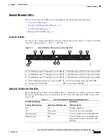
You can use the switch module LEDs to monitor switch module activity.
Figure 1-2
displays the LEDs
that are described in
Table 1-1
,
Table 1-2
, and
Table 1-3
.
Figure 1-2
Switch Module LEDs and System Activity LEDs
Uplink 10 Gb Ethernet Port LEDs
The Switch Module port LEDs are described in
Table 1-1
. Each of the six uplink ports has two LEDs.
The Activity LED blinks green or is off to indicate link activity. The Link Status LED is either solid
green or off.
1
10 Gb Ethernet port 15 Link and Activity LED
2
10 Gb Ethernet port 16 Link and Activity LED
3
10 Gb Ethernet port 17 Link and Activity LED
4
10 Gb Ethernet port 18 Link and Activity LED
5
10 Gb Ethernet port 19 Link and Activity LED
6
10 Gb Ethernet port 20 Link and Activity LED
7
Out-of-band management port Activity LED
8
Out-of-band management port Link LED
9
System Status Fault LED
10
System Status OK LED
1
2
3
4
5
6
8
7
9
10
192852
Table 1-1
Port LED Indications During Normal Operation
Port LED Indications
Port Status
Activity LED Indication
Link Status LED Indication
LED Description
Off
Off
No link established
Off
Solid green
No activity but link established
Blinking green
Solid green
Activity (traffic) on an established link
Blinking green
Off
Activity (traffic) on an established link
and port disabled (error disabled, STP
blocked)


