background image


5-17

Cisco Network Convergence System 4000 Series Hardware Installation Guide

Chapter 5      Installing Route Processor Cards, Fabric Cards, and Line Cards

  About Line Cards

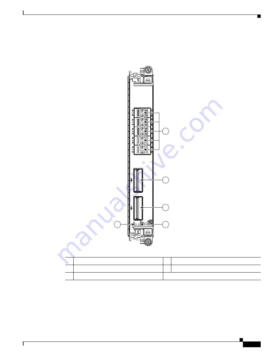
Figure 5-7

 shows the details of the front panel of the 2-port 100Gbps and 10-port 10 Gbps OTN and 

packet line card.

Figure 5-7

Front Panel of the 2-Port 100 Gbps and 10-Port 10 Gbps OTN and Packet Line Card

1. Port LEDs are triangular in shape and point toward the port that they support.

4

3

2

5

363614

1

1

Port LEDs (one LED on each port)

1

2

CPAK 1 port

3

CPAK 0 port

4

Status LED

5

Attention LED

Summary of Contents for NCS 4009

Page 1: ...has more than 200 offices worldwide Addresses phone numbers and fax numbers are listed on the Cisco website at www cisco com go offices Cisco Network Convergence System 4000 Series Hardware Installation Guide November 2015 Text Part Number ...

Page 2: ...y be required to correct any interference to radio or television communications at your own expense You can determine whether your equipment is causing interference by turning it off If the interference stops it was probably caused by the Cisco equipment or one of its peripheral devices If the equipment causes interference to radio or television reception try to correct the interference by using o...

Page 3: ...t Requirements 2 8 Chassis Cable Management 2 10 Safety Guidelines 2 10 Preventing Electrostatic Discharge 2 11 C H A P T E R 3 Site Planning Considerations 3 1 Basic Site and Installation Planning 3 1 Equipment Rack Considerations 3 2 Aisle Spacing and Maintenance Access Floor Plan 3 3 Front and Rear Clearances 3 4 Cable Management 3 4 Route Processor Cables 3 4 Interface Cables 3 5 Noise Control...

Page 4: ...ecting AC Power 4 28 Reconnecting AC Power 4 28 Disconnecting DC Power 4 29 Reconnecting DC Power 4 30 Powering On the Chassis 4 30 C H A P T E R 5 Installing Route Processor Cards Fabric Cards and Line Cards 5 1 About Installing Cards and Associated Components 5 1 Preventing Electrostatic Discharge 5 1 Guidelines for Installing and Removing a Card 5 2 Installing and Removing a Filler Card 5 3 Ins...

Page 5: ... H A P T E R 6 Removing and Replacing Chassis Components 6 1 Removing a Line Card 6 1 Removing an RP Card 6 3 Removing a Fabric Card 6 5 Removing the Power Components 6 7 Removing AC Input Power Cords 6 8 Removing DC Input Power Cables 6 8 Removing a Power Module Slot Cover 6 9 Removing an AC or DC Power Module 6 10 Removing an AC or DC Power Tray 6 11 Removing the Chassis Ground Cable 6 12 Replac...

Page 6: ... Electrostatic Discharge 8 11 C H A P T E R 9 Installing Power Components 9 1 Power Connection Guidelines 9 1 AC Powered Chassis 9 2 DC Powered Chassis 9 2 NEBS Supplemental Unit Bonding and Grounding Guidelines 9 5 Installing the Chassis Ground Cable 9 7 Installing an AC or DC Power Tray 9 9 Installing Power Modules 9 10 Installing AC or DC Power Modules 9 11 Installing the DC Power Front Connect...

Page 7: ...11 Installing a Fabric Card 10 11 Verifying the Installation of a Fabric Card 10 14 About Line Cards 10 15 24 Port Low Rate OTN Line Card 10 15 20 Port 10GE OTN Line Card 10 17 2 Port 100GE OTN Line Card 10 19 2 Port 100GE DWDM Line Card 10 21 Pluggable Optics Support 10 23 Installing a Line Card 10 24 Installing a Line Card 10 24 Verifying the Installation of a Line Card 10 27 Connecting Line Car...

Page 8: ... 11 15 Replacing the Fan Tray 11 20 Replacing the Craft Panel 11 22 Replacing the External Connection Unit 11 25 Replacing an SSD 11 26 A P P E N D I X C System Product IDs C 1 Component Product IDs C 1 Line Card Product IDs C 2 Cosmetic Product IDs C 2 Accessory Product IDs C 3 A P P E N D I X D System Specifications D 1 Chassis Specifications D 1 Power Specifications D 2 Environmental Specificat...

Page 9: ...s This document uses the following conventions Convention Indication bold font Commands and keywords and user entered text appear in bold font italic font Document titles new or emphasized terms and arguments for which you supply values are in italic font Elements in square brackets are optional x y z Required alternative keywords are grouped in braces and separated by vertical bars x y z Optional...

Page 10: ...are of the hazards involved with electrical circuitry and be familiar with standard practices for preventing accidents Use the statement number provided at the end of each warning to locate its translation in the translated safety warnings that accompanied this device SAVE THESE INSTRUCTIONS Warning Statements using this symbol are provided for additional information and to comply with regulatory ...

Page 11: ...ining Documentation and Submitting a Service Request Subscribe to What s New in Cisco Product Documentation which lists all new and revised Cisco technical documentation as an RSS feed and delivers content directly to your desktop using a reader application The RSS feeds are a free service ...

Page 12: ...xii Cisco Network Convergence System 4000 Series Hardware Installation Guide Preface Obtaining Documentation and Submitting a Service Request ...

Page 13: ...tic door should be removed Cisco Network Convergence System 4000 Series Unpacking Moving and Securing Guide 2 Ground the chassis Installing the Chassis Ground Cable section on page 4 8 3 Verify that the power components are installed Chapter 4 Installing Power Components 4 Verify that the ECU is installed Replacing the External Connection Unit page 6 28 5 Verify that the fan trays are installed Re...

Page 14: ...1 2 Cisco Network Convergence System 4000 Series Hardware Installation Guide Chapter 1 Installation Roadmap ...

Page 15: ... fabric cards FCs The Cisco NCS 4016 chassis is rack mountable It is compatible with the following standard rail spacing ANSI 19 inch or 23 inch ETSI Note For the ANSI 19 inch rack the minimum front opening must be 17 72 inches 450 mm to allow for chassis insertion The installation kit includes different brackets for each type of rack The Cisco NCS 4016 chassis contains its own power and cooling s...

Page 16: ...gence System 4000 Series Hardware Installation Guide Chapter 2 Chassis Overview About the Cisco NCS 4016 Chassis Figure 2 1 shows the front view of the Cisco NCS 4016 chassis Figure 2 1 Front View of the Cisco NCS 4016 Chassis ...

Page 17: ... partial rear views of the Cisco NCS 4016 chassis Note There are two air outlets on the rear of the chassis One is at the top behind the ECU and one is below the bottom fan tray 1 Power trays 2 4 Fiber management areas 2 2 External connection unit ECU Craft panel is attached on top of the ECU not shown see Figure 2 2 Air outlet is on back not shown see Figure 2 3 and Figure 2 4 5 Card cages 2 each...

Page 18: ...vergence System 4000 Series Hardware Installation Guide Chapter 2 Chassis Overview About the Cisco NCS 4016 Chassis Figure 2 3 Rear View of the Cisco NCS 4016 AC Chassis Figure 2 4 Rear View of the Cisco NCS 4016 DC Chassis ...

Page 19: ... monitor system alarms and control the system fans The LEDs on the front panel indicate active alarm conditions fabric cards FCs Four FCs are inserted into the front of the chassis The FCs provide the switch fabric for the routing system and performs the cross connect function of the routing system connecting every LC to each other The switch fabric receives ingress user data from one LC slot and ...

Page 20: ...nt air filters are located in the middle of the chassis behind the plastic inlet grill One is dedicated to the top card rack and the other to the bottom card rack We recommend that you change the air filter every three months The filter is sold in packs of 5 Cisco PID NCS4K FTF power trays Two power trays provide redundant power to the chassis Both AC and DC power trays are available Each power tr...

Page 21: ...section identifies the location and slot numbers for the cards and power modules that plug into the chassis Figure 2 6 Cisco NCS 4016 Chassis Slot Numbers Note Cards in the top and bottom card cages are not inserted in the same direction If you consider the top cards in Figure 2 6 as a reference cards in the bottom card cage are inserted upside down ...

Page 22: ...m of the chassis One air inlet and two air outlets Eight power modules for redundancy The upper four AC or DC power trays 0 3 are contained within power shelf 0 PS0 and the lower four AC or DC power trays 4 7 are contained within power shelf 1 PS1 The cards have electrical plugs at the back that plug into electrical connectors on the shelf backplane When the ejectors are fully closed the card plug...

Page 23: ...esponding symbol The symbol on the card must match the symbol on the slot Table 2 2 shows the slot and card symbol definitions Table 2 2 Slot and Card Symbols Symbol Color Shape Definition Orange Circle Slots LC0 through LC15 Only install line cards with a circle symbol on the faceplate Pink Triangle Slots LC0 through LC15 Only install line cards with circle or a triangle symbol on the faceplate B...

Page 24: ... area clear and dust free during and after installation Do not allow dirt or debris to enter into any laser based components Keep tools and chassis components away from walk areas Do not wear loose clothing jewelry and other items that could get caught in the chassis while working with the chassis and its components Use Cisco equipment in accordance with its specifications and product usage instru...

Page 25: ... Connect the equipment end of the connection cord to an ESD jack Figure 2 8 and Figure 2 9 or a bare metal surface on the chassis ensure the chassis is grounded Handle a card by its ejector levers when applicable or its metal carrier only avoid touching the board or connector pins Place a removed card board side up on an antistatic surface or in a static shielding bag If you plan to return the com...

Page 26: ...000 Series Hardware Installation Guide Chapter 2 Chassis Overview Safety Guidelines Figure 2 9 shows the ESD jacks on the bottom of the chassis Figure 2 9 ESD Jacks Bottom of Chassis 1 Bottom ANSI jacket point 2 Bottom ETSI connection point ...

Page 27: ...r for the routing system Can the routing system be positioned close to the AC or DC power source and are the power receptacles easy to reach Does the site have appropriate equipment racks with space available in which to install the system Are additional equipment racks required Is there a scissor lift or similar lifting device available to lift the chassis into the equipment rack In addition make...

Page 28: ...or routing system cables Equipment Rack Considerations A fully loaded Cisco NCS 4016 chassis weighs 412 lb 187 kg The chassis is mounted in a two post or a four post rack Figure 3 1 shows a four post rack Figure 3 1 Cisco NCS 4016 Chassis Mounted in an Equipment Rack 1 Equipment rack 3 Vertical mounting brackets 2 Cisco NCS 4016 chassis 4 Horizontal mounting brackets 122781 CISCO CRS 1SERIES LINEC...

Page 29: ...mounting brackets Note If you plan to use mounting screws other than the ones shipped with the chassis you can use 10 32 10 24 12 24 or M5 screws M6 and 1 4 20 screws do not fit The rack should have horizontal shelf brackets to place the chassis on The brackets must be able to support at least 650 lb 294 8 kg If the rack does not have horizontal mounting rails a set of rails is included in the ins...

Page 30: ...s routing systems should be arranged to minimize the complexity and length of the cable runs Precut and terminated cables are considered part of the basic configuration CONSOLE or AUX RJ 45 RS 232 serial ports on the route processor cards for terminal connections Ethernet ports on the route processor cards for connecting network management equipment Modular service cards MSCs and physical layer in...

Page 31: ... 4016 chassis has some built in noise reduction such as fan speed control If the routing system is installed in an environment where excessive noise could be harmful to personnel some other noise reduction options could be attempted Passive noise reduction could include the installation of foam panels to insulate the surrounding area from the noise Additional noise reduction measures have to be de...

Page 32: ...3 6 Cisco Network Convergence System 4000 Series Routers Site Planning Guide Chapter 3 Site Planning Considerations System Testing Certification and Warranties ...

Page 33: ...ting Power to the Chassis page 4 23 Disconnecting AC or DC Power page 4 28 Powering On the Chassis page 4 30 Power Connection Guidelines You can configure the chassis with either an AC input or DC input power subsystem so the site power source requirements differ depending on the power subsystem in your chassis Ensure all power connection wiring conforms to the rules and regulations in the Nationa...

Page 34: ...at the circuit breaker and fuse lockout procedures should follow the rules and regulations in the National Electrical Code NEC and any local codes For a list of the nominal and acceptable value ranges for source AC power see Table B 2 The Cisco NCS 4016 chassis supports two types of AC power cords International and NEMA USA Figure 4 1 International AC Power Cord Cisco PID NCS4K AC CBL IEC Figure 4...

Page 35: ... available from any commercial cable vendor You must terminate DC power cables using cable lugs at the power tray end The appropriate lugs are provided in the installation kit with 6 AWG cable Use Panduit part number LCD4 14AF L or the equivalent Warning Hazardous voltage or energy may be present on power terminals Always replace cover when terminals are not in service Be sure uninsulated conducto...

Page 36: ...e DC cable leads might have a positive or a negative label This is a relatively safe indication of the polarity but you must verify the polarity by measuring the voltage between the DC cable leads Be sure that the positive and negative cable leads match the positive and negative labels on the power module when making the measurement A green or green and yellow cable typically indicates that it is ...

Page 37: ...source requires its own circuit breaker Each power source must provide clean power to the site If necessary install a power conditioner The site must provide short circuit over current protection for devices Proper grounding is required at the site to ensure that equipment is not damaged by lightning and power surges In addition Chassis grounding is required for AC and DC powered systems For AC po...

Page 38: ...to only one shelf but will not have N N redundancy Each AC power source must provide single phase AC power and have its own circuit breaker The AC power receptacles used to plug in the chassis must be the grounding type The grounding conductors that connect to the receptacles should connect to protective earth ground at the service equipment AC single phase input Single phase 200 to 240 VAC nomina...

Page 39: ...quirements for supplemental bonding and grounding connections If you are not installing the chassis in a NEBS environment you can choose to bypass these guidelines and rely on the safety earth ground connections to the AC power modules Figure 4 4 shows the NEBS bonding and grounding points on the NCS 4016 chassis Figure 4 4 NEBS Bonding and Grounding Points on the Cisco NCS 4016 Chassis 1 NEBS gro...

Page 40: ... is ideal One grounding wire Although we recommend at least 2 4 AWG multistrand copper wire the wire diameter and length depend on your chassis location and site environment Note These parts are not available from Cisco with the exception of the grounding lug but they are available from commercial vendors Installing the Chassis Ground Cable This section describes how to install a ground cable to e...

Page 41: ...frame and chassis DC I Isolated DC Return Figure 4 5 Straight Barrel Grounding Lug Steps To attach the ground cable to the chassis perform the following steps Step 1 Use the crimping tool mandated by the lug manufacturer to crimp the lug to the ground cable Step 2 Use the socket wrench to attach the lug and ground cable to either grounding point Figure 4 6 and Figure 4 7 Note The two grounding poi...

Page 42: ...ssis Ground Cable Figure 4 6 Attaching to Front NEBS Bonding and Grounding Point Figure 4 7 Attaching to Side NEBS Bonding and Grounding Point Step 3 Use the torque wrench to tighten the bolts to a torque of 35 in lb 3 95 N m 363918 1 2 1 Screws 2 Lock washers 1 NEBS grounding point on right side of the chassis 2 Screws 3 Lock washers ...

Page 43: ...y in the chassis Required Tools and Equipment 6 inch number 1 Phillips screwdriver Cisco NCS 4016 power trays NCS4K AC PEM or NCS4K DC PEM Steps Follow these steps to install an AC or DC power tray into the chassis Step 1 Slide the power tray into the bay until it engages its mating connector on the chassis Step 2 Fully seat the power tray into its mating connector and seat the power tray mounting...

Page 44: ...is The installation procedure is the same for both AC or DC modules Caution Never force a power module into the power tray if you feel any resistance The power modules are keyed to prevent AC modules from being plugged into a DC power tray or a DC module into an AC power tray Forcing a module into the incorrect tray can cause damage to the module and the tray Each power module has three status LED...

Page 45: ...stall the AC or DC power modules into the chassis Step 1 Remove the filler caps from the slots where you want to install the power modules Step 2 Using two hands to support the power module slide it into the power tray Table 4 1 Power Module LED Status Indicator Lights LED Name Color Meaning Input OK Green On The input voltage is present and within regulation range Blinking The input voltage is pr...

Page 46: ...System 4000 Series Hardware Installation Guide Chapter 4 Installing Power Components Installing Power Modules Figure 4 9 Example of Inserting the AC Power Module Step 3 Secure the power module into the power tray using the snap hook ...

Page 47: ...ok AC Step 4 Repeat these steps for the other AC or DC power modules Installing the DC Power Front Connection Adapter If you have limited access to the back of the chassis or limited space behind the chassis you can use the DC Power Front Connection Adapter This DC adapter moves the DC power connections from the back of the chassis to the front of the chassis This may be desirable in ETSI rack ins...

Page 48: ...n a rack or cabinet The Cisco NCS 4016 chassis should be completely removed from the packaging and installed in the rack or cabinet Required Tools and Equipment 6 inch number 1 Phillips screwdriver One DC Power Front Connection Adapter NCS4K DC FA includes brackets 3 8 Ratchet Wrench 7 16 Socket and a Torque Wrench Steps Step 1 Install the DC FA front access brackets on the sides toward the front ...

Page 49: ...apter 4 Installing Power Components Installing the DC Power Front Connection Adapter Figure 4 12 Installing the DC FA Brackets Step 2 Attach the rear cable guide on top of the chassis toward the rear and attach the insulator sheet on top of the chassis toward the front Figure 4 13 ...

Page 50: ...Installing Power Components Installing the DC Power Front Connection Adapter Figure 4 13 Attaching Rear Cable Guide and Insulator Sheet Step 3 Place the DC adapter on top of the chassis using the embossed references on the top chassis cover Figure 4 14 1 Rear cable guide 2 Insulator sheet ...

Page 51: ...ponents Installing the DC Power Front Connection Adapter Figure 4 14 Placing DC Adapter on Top of Chassis Step 4 Connect the power cables on the rear of the of DC adapter to the chassis terminal blocks Figure 4 15 Follow the connections scheme as shown on the labels available on the DC adapter and the chassis ...

Page 52: ...re Installation Guide Chapter 4 Installing Power Components Installing the DC Power Front Connection Adapter Figure 4 15 Connecting Power Cables Step 5 Install the rear cover to protect the cables Figure 4 16 1 Connect power cables to chassis terminal blocks ...

Page 53: ...uide Chapter 4 Installing Power Components Installing the DC Power Front Connection Adapter Figure 4 16 Installing the Rear Cover Step 6 Install the chassis and DC adapter subassembly in the rack or cabinet Attach the chassis brackets and DC brackets to the rack Figure 4 17 ...

Page 54: ...ction Adapter Figure 4 17 Chassis Brackets and DC Adapter Brackets Step 7 Connect the power cables coming from batteries or from the PDU unit to the DC adapter terminal blocks on the front side of the unit Figure 4 18 See the Connecting Power to the Chassis section on page 4 23 1 DC adapter brackets 2 Chassis brackets one on other side is not visible ...

Page 55: ... of the following procedures to connect power to your chassis Connecting Power to an AC Powered Chassis page 4 23 Connecting Power to a DC Powered Chassis page 4 25 Connecting Power to an AC Powered Chassis Follow these steps to connect the AC power cords to the chassis Note Connect each AC power supply to a dedicated power source branch circuit Each AC input power supply operates at a nominal inp...

Page 56: ...office grounding system has been installed to the NEBS grounding location on the chassis Warning To ensure that power remains off while you are performing this procedure lock out tag out the circuit breaker switch in the OFF 0 position until you are ready to turn it on Step 4 Plug the AC power cord into the receptacle at the rear of the AC power tray Step 5 Tighten the screw that clamps the AC pow...

Page 57: ... that power remains off while you are performing this procedure lock out tag out the DC circuit breaker switch in the OFF 0 position until you are ready to turn it on Follow these steps to connect the DC source power cables to a DC power tray Step 1 Verify that the power switch is set to the OFF 0 position The power switch is on the right of the power tray Step 2 Remove the clear plastic safety co...

Page 58: ... that secure the DC power cables to the power tray terminals The nuts should be tightened using the 7 16 hex socket and torque wrench to a torque of 45 to 50 in lb Figure 4 20 DC Power Tray Rear Panel Figure 4 21 Typical Power Connections to a Power Tray for a Single DC Power Module Power System Step 6 Replace the clear plastic safety covers over the connection terminal studs 364881 ...

Page 59: ...nvergence System 4000 Series Hardware Installation Guide Chapter 4 Installing Power Components Connecting Power to the Chassis Figure 4 22 Typical Plastic Safety Covers over the Power Tray Connection Terminals 364882 364883 ...

Page 60: ...ged while the system is powered from other AC power sources If it becomes necessary to disconnect all AC power from the chassis follow these steps Caution Do not disconnect all power from the chassis to replace components including power modules See Chapter 6 Removing and Replacing Chassis Components Step 1 Set the power switch at the rear of the AC power tray to the OFF 0 position Step 2 Power of...

Page 61: ...ir terminals in the following order and note the color of each cable a Negative PWR cables first b Positive RTN cables last Step 4 Repeat Step 1 through Step 3 for the other power module distribution that needs to be removed If it becomes necessary to disconnect all DC power from the chassis follow these steps Note This procedure describes how to disconnect DC power from all power modules in a sin...

Page 62: ...hese steps to turn on power to an AC powered or DC powered chassis Step 1 Power on the circuit breaker to your power sources one at a time Step 2 Verify that the correct Power Input LED on each power module in the tray is lit one input on the LED flashes and both inputs on the LED are solid Continue with steps 1 and 2 until all inputs have been verified Note On the DC power tray the Power Input LE...

Page 63: ... RP page 5 34 About Installing Cards and Associated Components Preventing Electrostatic Discharge page 5 1 Guidelines for Installing and Removing a Card page 5 2 Preventing Electrostatic Discharge Electrostatic discharge ESD damage which can occur when electronic cards or components are improperly handled results in complete or intermittent failures We recommend use of an ESD preventive wrist stra...

Page 64: ...nds of the faceplate When you remove a card press the OIR buttons before using the ejector levers to ensure that the connector pins disconnect from the backplane in the sequence expected by the chassis The correct card orientation is shown by the eject symbol on the OIR buttons The symbol must be oriented upward for cards in the top row and downward for cards in the bottom row Every FC LC and RP c...

Page 65: ...nd FC slots Caution To ensure thermal regulation in the chassis keep filler cards installed in all slots that do not have an RP LC or FC installed This section contains the following procedures Installing a Filler Card page 5 3 Removing a Filler Card page 5 5 Installing a Filler Card This section describes how to install a filler card in the Cisco NCS 4016 chassis Prerequisites Before performing t...

Page 66: ... Use both hands while inserting a filler card Use one hand on the faceplate and the other hand along the base of the filler card to guide it into the slot Step 3 Slide the filler card into the chassis until the captive screw plates are flush with the chassis Step 4 Partially tighten the two captive screws on the front panel of the filler card either by hand or with the number 2 Phillips screwdrive...

Page 67: ...d under the filler card to guide it Step 4 Holding the filler card underneath and by the handle pull it from the slot and set it carefully aside About RP Cards The Cisco NCS 4016 chassis supports two route processors RPs These cards provide the intelligence of the system by functioning as the shelf controllers for DWDM or OTN applications and by providing route processing and chassis management Th...

Page 68: ...two RP cards in dedicated slots on the right side of the chassis The RP cards are identical One RP card installs into slot RP0 on the top side of the chassis and the second RP card installs into slot RP1 on the bottom side of the chassis The RP cards are hot swappable Note Orientation of the RP card when inserted into the chassis varies depending upon whether you are inserting the card into the up...

Page 69: ...eries Hardware Installation Guide Chapter 5 Installing Route Processor Cards Fabric Cards and Line Cards Installing an RP Card Figure 5 2 Installing an RP Card 1 Direction and location of insertion 3 Captive screws 2 Ejector levers 4 OIR buttons ...

Page 70: ...ges of the card cage and then stop when the ejector lever hooks catch the card cage If they do not catch try reinserting the RP until the ejector lever hooks are fully latched Step 6 Press the OIR buttons to release the ejectors Step 7 Pivot both card ejector levers so that the openings on the card ejector cams at the top and bottom of the card pass over the tabs on each side of the card cage slot...

Page 71: ...P Card This section describes how to verify that the RP card has been properly installed and how to troubleshoot the installation in the Cisco NCS 4016 chassis Figure 5 3 shows the front panel of the RP card Figure 5 3 RP Card Front Panel 1 Status LED card status indicator 8 Active Standby LED 2 Attention LED 9 Acknowledge button 3 Sync LED 10 Lamp test button 4 Disc LED 11 External USB port 5 Cri...

Page 72: ... Ensure that the card is seated firmly in the Cisco NCS 4016 chassis slot One easy way to verify physical installation is to see whether the front faceplate of the card is even with the fronts of the other cards installed in the card cage Ensure that the ejector levers are latched and that the captive screws are fastened properly If you are uncertain unlatch the levers loosen the screws and attemp...

Page 73: ...system connecting every LC to each other The switch fabric receives ingress user data from one LC slot and performs the switching necessary to route the data to the appropriate egress LC slot Twelve pluggable front panel connections allow a single chassis system to migrate to a back to back or multi chassis configuration See the Verifying the Installation of a Fabric Card section on page 5 15 for ...

Page 74: ...r 2 Phillips screwdriver or number 2 common flat head screwdriver FC Cisco PID NCS4016 FC M Steps The following steps describe how to install an FC card Figure 5 4 Installing an FC Step 1 Attach the ESD preventive wrist strap to your wrist and connect its leash to one of the two ESD jacks located on the front or rear side of the chassis You can also connect the ESD preventive wrist strap leash to ...

Page 75: ... tabs otherwise one or both ejector levers might bind when you attempt to close the levers thereby damaging or breaking one or both of them Step 8 Continue sliding the card into the card cage slot until the openings on the card ejector cams engage the tabs on each side of the card cage slot Note FCs have guide pins that make initial contact with the backplane connector as you slide a card into its...

Page 76: ...ystem 4000 Series Hardware Installation Guide Chapter 5 Installing Route Processor Cards Fabric Cards and Line Cards Installing a Fabric Card Figure 5 5 Attaching the Vertical Cable Management Bracket 1 Dark gray arm 2 Light gray arm ...

Page 77: ...llation of the card When the card is properly installed and no faults are detected the card status LED turns green When the card status LED is solid yellow either software initialization is in progress during bootup or a fault exists on the board When the card status LED is blinking yellow the card is not fully seated When the card status LED is off verify that the card is installed correctly Ther...

Page 78: ... following line cards 2 Port 100Gbps and 10 Port 10Gbps OTN and Packet Line Card page 5 16 24 Port Low Rate OTN Line Card page 5 18 20 Port 10GE OTN Line Card page 5 20 2 Port 100GE OTN Line Card page 5 22 2 Port 100GE DWDM Line Card page 5 24 For a list of the pluggable optics that are supported see the Pluggable Optics Support section on page 5 26 2 Port 100Gbps and 10 Port 10Gbps OTN and Packet...

Page 79: ...ows the details of the front panel of the 2 port 100Gbps and 10 port 10 Gbps OTN and packet line card Figure 5 7 Front Panel of the 2 Port 100 Gbps and 10 Port 10 Gbps OTN and Packet Line Card 1 Port LEDs are triangular in shape and point toward the port that they support 4 3 2 5 363614 1 1 Port LEDs one LED on each port 1 2 CPAK 1 port 3 CPAK 0 port 4 Status LED 5 Attention LED ...

Page 80: ...92 OTU2 interfaces through SFP pluggable optics OTU1 and OTU2 ports support generic forward error correction GFEC The card supports ODU2 ODU1 ODU0 and ODUFlex switching functions by interconnecting with the centralized agnostic switch fabric Figure 5 8 shows the details of the front panel of the 24 port low rate OTN LC and LEDs Table 5 2 2 Port 100 Gbps and 10 Port 10 Gbps OTN and Packet Line Card...

Page 81: ... Rate OTN LC Front Panel and LEDs 1 Port LEDs are triangular in shape and point toward the port that they support 1 Status LED 3 Port LEDs one LED on each port 1 2 Attention LED Table 5 3 24 Port Low Rate OTN LC Descriptions LED State Description Status Green The LC is properly seated and operating correctly Yellow The LC has one or more errors detected Off No power is applied to the LC ...
Page 82: ...TU2 interfaces through SFP pluggable optics OTU1 and OTU2 ports support generic forward error correction GFEC The card supports up to 2 level ODU4 ODU3 ODU2 ODU1 ODU0 and ODUFlex switching functions by interconnecting with the centralized agnostic switch fabric The line card also supports direct interconnection to other slots within the Cisco NCS 4016 chassis to interconnect switched OTN traffic d...

Page 83: ... 10GE OTN LC Front Panel and LEDs 1 Port LEDs are triangular in shape and point toward the port that they support 1 Status LED 3 Port LEDs one LED on each port 1 2 Attention LED Table 5 4 20 Port 10GE OTN LC Descriptions LED State Description Status Green The LC is properly seated and operating correctly Yellow The LC has one or more errors detected Off No power is applied to the LC ...

Page 84: ...acles are hosted on the faceplate Note Insert CPAK modules in the 2 port 100GE OTN LC handle side down The card supports up to two level ODU4 ODU3 ODU2 ODU1 ODU0 and ODUFlex nested switching functions by interconnecting with the centralized agnostic switch fabric 100 Gigabit Ethernet signals are mapped using generic mapping procedure GMP over ODU4 according to ITU T G 709 v3 Section 17 7 5 Figure ...

Page 85: ...rt 100GE OTN LC Front Panel and LEDs 1 Status LED 3 Port LEDs one LED on each port 2 Attention LED Table 5 5 2 Port 100GE OTN LC Descriptions LED State Description Status Green The LC is properly seated and operating correctly Yellow The LC has one or more errors detected Off No power is applied to the LC Attention1 Blue The card needs attention Off The card does not need attention ...

Reviews: