background image

Security Features

The MR55 features multiple options for physically securing the access point after installation:

1.

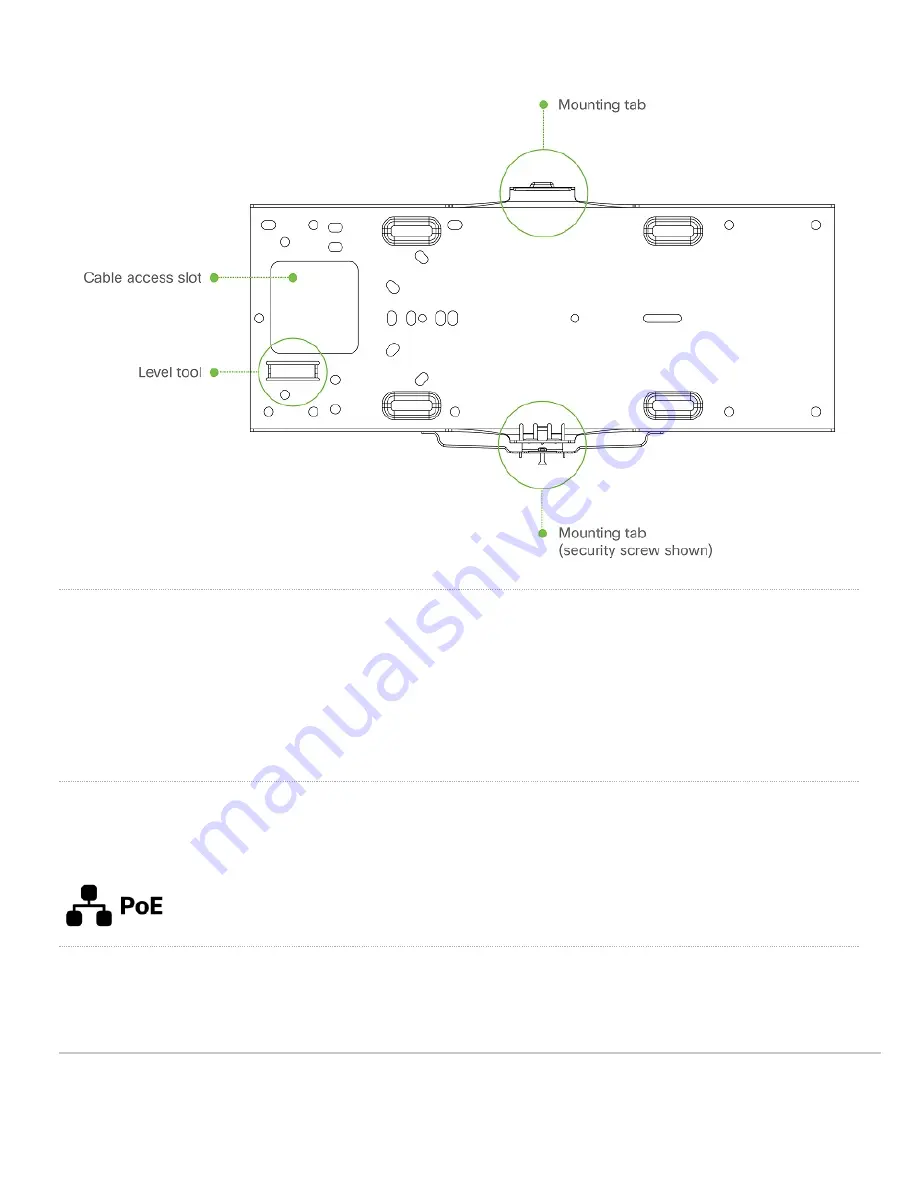
Security screw – The accessory kit includes screws that can be used to secure the access point to the mount cradle. Engaging the security screw
prevents accidental dislodging and theft.

2.

Kensington lock – The access point contains a hard point that allows it to be secured to any nearby permanent structure using a standard Kensington
lock.

Ethernet Ports

The MR55 features a Gigabit Ethernet RJ45 port that accepts 802.3at power (labeled “Eth0, PoE”). This port should be used for uplink to your WAN connection.

Power Source Options

The MR55 access point can be powered using either the Meraki AC Adapter, PoE Injector (both sold separately), or a third-party PoE switch.

6

Summary of Contents for Meraki MR55

Page 1: ...h density the MR55 meets the needs of the most demanding environments The access point also includes a third radio dedicated to optimizing the RF environment and securing the airwaves along with a BLE radio for supporting IoT applications Package Contents The MR55 package contains the following MR55 Cloud Managed Access Point Mount cradle including built in level tool 1 ...

Page 2: ... Drop ceiling mount kit Wall screws wall screw anchors and security screws 2 ...

Page 3: ...Understanding the MR55 Your Meraki MR55 has the following features 3 ...

Page 4: ...4 ...

Page 5: ...The mount cradle has the following features 5 ...

Page 6: ...g and theft 2 Kensington lock The access point contains a hard point that allows it to be secured to any nearby permanent structure using a standard Kensington lock Ethernet Ports The MR55 features a Gigabit Ethernet RJ45 port that accepts 802 3at power labeled Eth0 PoE This port should be used for uplink to your WAN connection Power Source Options The MR55 access point can be powered using either...

Page 7: ...brief overview only of the steps required to add an MR55 to your network For detailed instructions about creating configuring and managing Meraki wireless networks refer to the online documentation documentation meraki com 1 Login to http dashboard meraki com If this is your first time create a new account 2 Find the network to which you plan to add your APs or create a new network 3 Add your APs to...

Page 8: ...place it must allow outgoing connections on particular ports to particular IP addresses The most current list of outbound ports and IP addresses for your particular organization can be found here Assigning IP Addresses to MR55 All gateway MR55s MR55s with Ethernet connections to the LAN must be assigned routable IP addresses These IP addresses can be dynamically assigned via DHCP or statically ass...

Page 9: ...R55 to the PoE port of the Injector and the client machine to the LAN port 3 Using a web browser on the client machine access the AP s built in web server by browsing to http my meraki com Alternatively browse to http 10 128 128 128 4 Click on the Uplink Configuration tab Log in The default login is the serial number e g Qxxx xxxx xxxx with no password e g Q2DD 551C ZYW3 5 Configure the static IP ad...

Page 10: ...th of 300 ft 100 m 3 If being used in a mesh deployment the MR55 should have line of sight to at least two other Meraki devices A Cisco Partner can help ensure that your AP placement is ideal Install the MR55 For most mounting scenarios the MR55 mount cradle provides a quick simple and flexible means of mounting your device The installation should be done in two steps First install the mount cradle...

Page 11: ... to your mounting wall or ceiling It is recommended that the MR55 be mounted to a wall or solid ceiling using the mount cradle for physical security reasons Drop Ceiling Mount using Mount Cradle To mount your MR55 on a drop ceiling T rail use the included drop ceiling mounting accessory kit The accessory kit can be used to mount to most 9 16 15 16 or 1 T rails The kit contains Drop ceiling mountin...

Page 12: ... the dashed lines on the mount cradle template as a guide set the proper spacing of the T rail clips on the T rail 3 Tighten the set screws on the T rail clips to secure the clips using a 5 64 2 mm hex key 12 ...

Page 13: ...to an electrical junction box feed the Ethernet cable through the cable access hole in the mount cradle If mounting to a wall or ceiling the Ethernet cable will feed from behind the MR55 The Power Source Options section of this document lists the different powering options and their unique characteristics Mount the MR55 Attach the MR55 to the Mount Cradle This section applies to wall and or solid ...

Page 14: ...he MR55 to guide the MR55s bottom slot into the cradle s bottom tab until it clicks into place Once in place the MR55 should be secured to the cradle by using one of the included screws in the cradle s bottom tab 14 ...

Page 15: ...n the lower mount cradle tab Kensington Lock Attach a Kensington lock cable to the access point at the hard point on the side of the device Attach the other end of the cable to a secure location such as a pipe or building fixture Verify Device Functionality and Test Network Coverage 1 Check LEDs a The Power LED should be solid green or blue if clients are connected If it is flashing blue the firmware...

Reviews: