4 Upgrading DRAM on the CIP2
Upgrading DRAM on the CIP2
Step 5
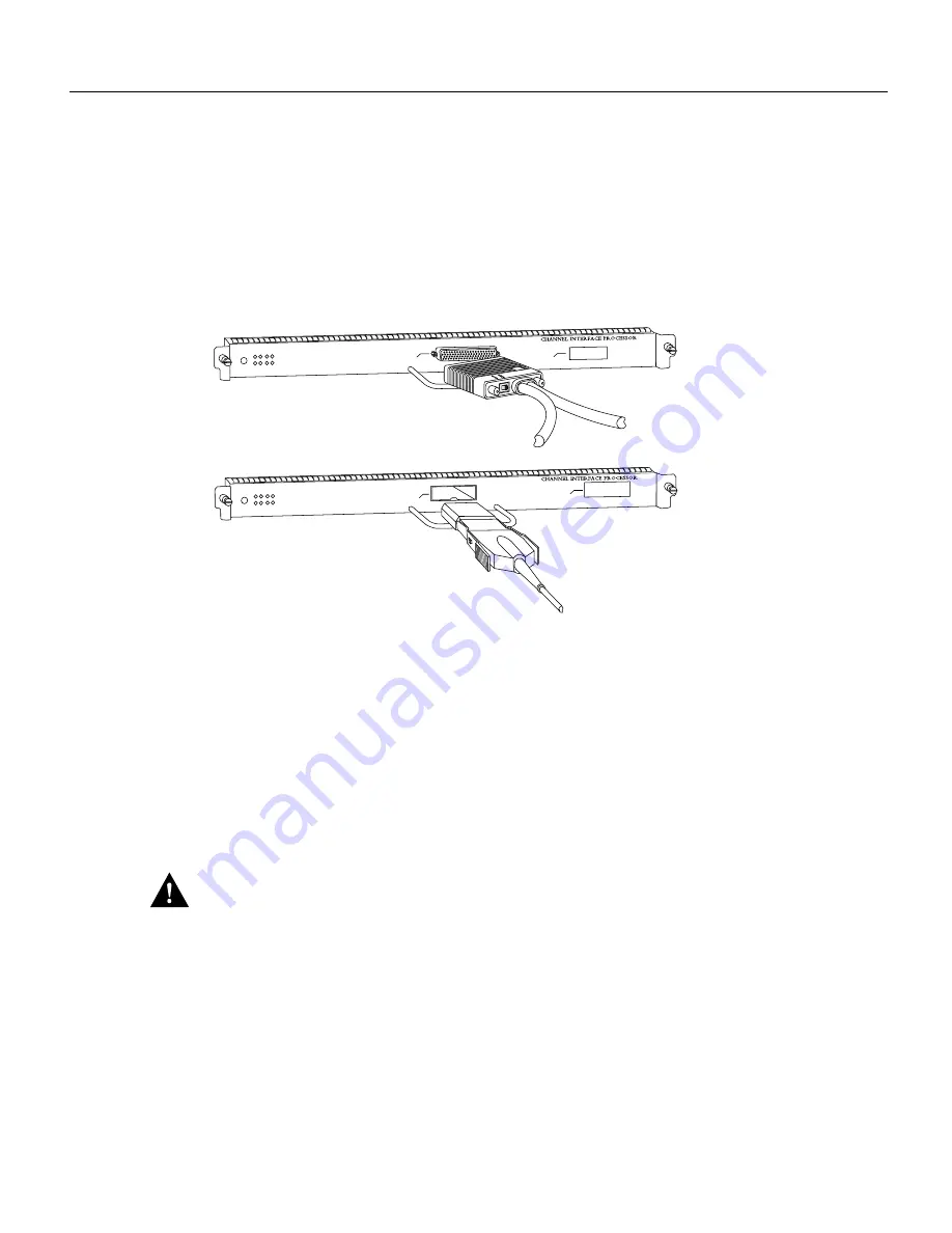
Disconnect the Y cable from each PCA and the ESCON cable from each ECA. (See
Figure 2.) Do not disconnect the V-type cables from the Y cable. To disconnect the Y cable
from the PCA, it might be necessary to temporarily remove any strain relief used to
support the V-type bus and tag cables, which are quite heavy. It should not be necessary
to disconnect the V-type cables from the Y cable. Make certain that you replace all strain
relief when you reconnect the Y cable to the PCA connector.
Figure 2
Disconnecting Cables from the CIP2
Step 6
Use the appropriate screwdriver to loosen both the captive installation screws on the CIP2
or interface processor filler. (See Figure 3a on page 5.)
Step 7
Place your thumbs on the ends of each of the ejector levers and simultaneously pull them
both outward, away from the interface port (in the opposite direction from that shown in
Figure 3c on page 5) to release the carrier from the slot. This action also releases the CIP2
bus connector from the backplane.
Step 8
Grasp the handle with one hand and pull the CIP2 straight out of the slot, keeping your
other hand under the carrier to guide it. Keep the carrier parallel to the backplane. Avoid
touching the card or any connector pins.
Caution
Always use the ejector levers when installing or removing interface processor modules. A
module that is partially seated in the backplane will cause the system to halt and subsequently crash,
and shoving or slamming the interface processor into the slot can damage the backplane and pins.
Step 9
Place the removed CIP2 on an antistatic mat or foam pad (or in an antistatic bag if you
need to return the CIP2 to the factory for any reason).
1
CIP with an ECA
0
H2673
ESCON cable
0
1
CIP with a PCA
Y cable


