Cisco ME 1200 Series Hardware Installation Manual Download Page 24

2-10

Cisco ME 1200 Series Carrier Ethernet Access Devices Hardware Installation Guide

OL-31962-04

Chapter 2      Installing the Cisco ME 1200 NID

Installing and Removing SFP Modules

Note

We strongly recommend that you do not install or remove fiber-optic SFP modules with cables attached 
because of the potential damage to the cables, the cable connector, or the optical interfaces in the SFP module. 
Disconnect all cables before removing or installing an SFP module. Removing and installing an SFP module 
can shorten its useful life. Do not remove and insert SFP modules more often than is absolutely necessary.

Figure 2-7

SFP Module with a Bale-clasp Latch

Step 1

Attach an ESD-preventive wrist strap to your wrist and to a bare metal surface. Find the send (TX) and receive 
(RX) markings that identify the top side of the SFP module.

Step 2

On some SFP modules, the send and receive (TX and RX) markings might be replaced by arrows that show 
the direction of the connection, either send or receive (TX or RX).

Step 3

Align the SFP module in front of the slot opening and push until you feel the connector on the module snap 
into place in the rear of the slot (see Figure 2-8).
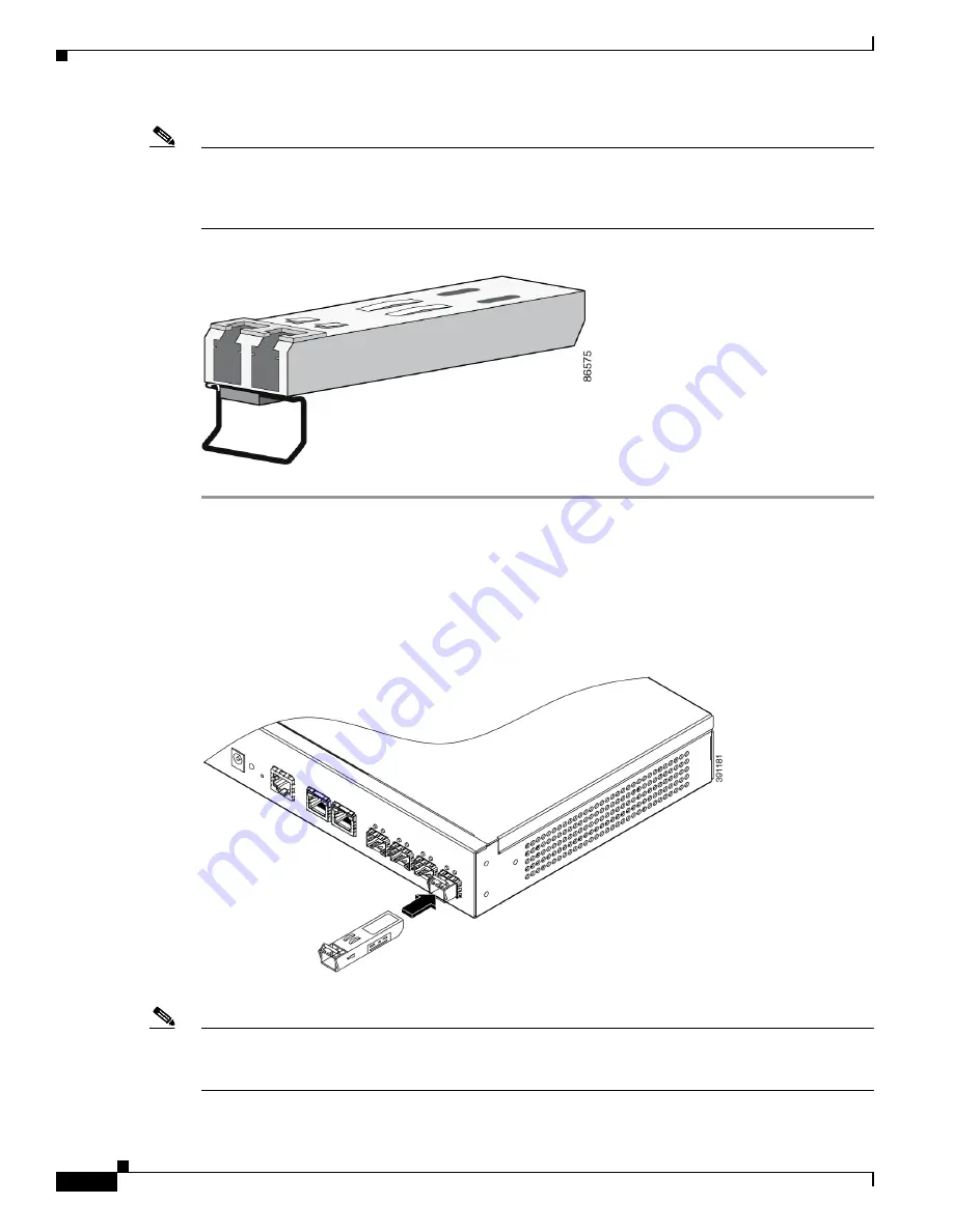
Figure 2-8

Installing a SFP Module into a SFP Module Slot

Step 4

For fiber-optic SFP modules, remove the dust plugs from the optical ports, and store them for later use.

Note

Do not remove the dust plugs from the fiber-optic SFP module port or the rubber caps from the 
fiber-optic cable until you are ready to connect the cable. The plugs and caps protect the SFP module 
ports and cables from contamination and ambient light.

Summary of Contents for ME 1200 Series

Page 1: ... than 200 offices worldwide Addresses phone numbers and fax numbers are listed on the Cisco website at www cisco com go offices Cisco ME 1200 Series Carrier Ethernet Access Devices Hardware Installation Guide June 2017 Text Part Number OL 31962 04 ...

Page 2: ... are encouraged to try to correct the interference by using one or more of the following measures Reorient or relocate the receiving antenna Increase the separation between the equipment and receiver Connect the equipment into an outlet on a circuit different from that to which the receiver is connected Consult the dealer or an experienced radio TV technician for help Modifications to this product...

Page 3: ...ar Panel 1 5 Management Options 1 6 Management Option 1 1 6 Management Option 2 1 6 Management Option 3 1 6 Network Configurations 1 7 C H A P T E R 2 Warnings 2 1 Installation Guidelines 2 3 Verifying Switch Operation 2 4 Installation the Switch 2 4 Rack Mounting 2 4 Attaching Brackets to the Switch 2 4 Attaching Brackets to the Switch 2 6 Mounting in a Rack 2 6 Mounting the Switch using 19 inch ...

Page 4: ...nstalling an AC to DC Power Adapter 3 2 Wiring the DC Input Power Source 3 3 Grounding the Switch 3 4 C H A P T E R 4 Diagnosing Problems 4 1 Switch Performance 4 1 Speed Duplex and Auto negotiation 4 1 Auto negotiation and NICs 4 2 Cabling Distance 4 2 Finding the Switch Serial Number 4 2 Technical Specifications A 1 Environmental and Technical Specifications for the Switch A 1 Environmental and ...

Page 5: ...tall it and provides troubleshooting information This guide does not describe system messages that you might receive or how to configure your switch For more information see the switch Cisco NID Controller Guide on Cisco com at http www cisco com c en us support switches me 1200 series carrier ethernet access devices tsd pro ducts support general information html Note Means reader take note Notes ...

Page 6: ...isco Regulatory Compliance and Safety Information for Cisco ME 1200 Series Carrier Ethernet Access Devices Obtaining Documentation and Submitting a Service Request For information on obtaining documentation using the Cisco Bug Search Tool BST submitting a service request and gathering additional information see What s New in Cisco Product Documentation at http www cisco com en US docs general what...

Page 7: ...t Panel page 1 2 Rear Panel page 1 6 Management Options page 1 6 Setting Up the Switch This document covers switch management options basic rack mounting procedures port and module connections power connection procedures and troubleshooting Switch Models The Cisco ME1200 NID switches have fixed AC and DC power options Each switch has 4 1GE SFP Small Form factor Pluggable ports and two RJ 45 copper...

Page 8: ... debug information Console operation is not supported The serial port s configuration requirements are as follows Default Baud rate 115 200 bps Parity None Stop bit One Data bits 8 Flow control none 1 AC 100V to 240V Power input 4 Console port 2 DC 12 VDC Power input 5 10 100 1000Base T RJ 45 Port 3 RESET ZTP 6 100Base FX 1000Base X SFP Fiber Port 1 DC 20 5V to 72V Power input 4 Console port 2 DC ...

Page 9: ...ers on both ends of the connection For simplified cabling the automatic medium dependent interface crossover auto MDIX feature is enabled by default The switch detects the required cable type for copper Ethernet connections and configures the interface accordingly You can use either a crossover or a straight through cable for connections to a switch 10 100 1000 Ethernet port regardless of the type...

Page 10: ... GLC T1 1000M SFP CWDM SFP xxxx 8 colors 1000M SFP GLC BX U 1000M SFP GLC BX D 1000M SFP SFP GE L 1000M SFP SFP GE S 1000M SFP SFP GE Z 1000M SFP SFP GE T 1000M SFP GLC TE 1000M SFP DWDM SFP xxxx 40 wavelengths 1 The system can support a lower operating ambient temperature of 5o C with GLC T However cold boot with this module is supported only from 0o C Table 1 2 SFP Module Support 1 SYS system LE...

Page 11: ...in progress normal operation Alternating Green Off ZTP downloading Alternating Red Off ZTP failed Alternating Amber Off ZTP configuring Solid Red Software error Solid Amber System healthy working with redundant PSU Alternating Green Amber POST in progress Table 1 4 Port LEDs Color Port Status OFF RJ 45 SFP no link Left side LED Green RJ 45 SFP link on 1000Mbps Blinking Green RJ 45 SFP activity lin...

Page 12: ...ere are multiple options to manage the Cisco ME1200 NID Management Option 1 In this model there will be a Cisco UPE and a Cisco Edge device The NID will be downstream device on the Cisco UPE A UPE NID Controller software subsystem on the ME3600 UPE will be used to manage the NID Refer to the UPE NID Controller configuration guide for the ME3600 Management Option 2 In this model the UPE is not a Ci...

Page 13: ...ID There is no UPE and there is unlikely to be a UPE NID Controller subsystem in the ASR 9K Such customers may use PRIME or a 3rd party NMS Network Configurations See the switch software configuration guide on Cisco com for an explanation of network configuration concepts The software configuration guide also provides examples of network configurations that use the switch to create dedicated netwo...

Page 14: ...1 8 Cisco ME 1200 Series Carrier Ethernet Access Devices Hardware Installation Guide OL 31962 04 Chapter 1 Product Overview Management Options ...

Page 15: ... Warning Before working on equipment that is connected to power lines remove jewelry including rings necklaces and watches Metal objects will heat up when connected to power and ground and can cause serious burns or weld the metal object to the terminals Statement 43 Warning Do not stack the chassis on any other equipment If the chassis falls it can cause severe bodily injury and equipment damage ...

Page 16: ... as the main disconnecting device Statement 1019 Warning This equipment must be grounded Never defeat the ground conductor or operate the equipment in the absence of a suitably installed ground conductor Contact the appropriate electrical inspection authority or an electrician if you are uncertain that suitable grounding is available Statement 1024 Warning Only trained and qualified personnel shou...

Page 17: ...orts cable lengths from the switch to connected devices can be up to 328 feet 100 meters For cable requirements for 1000BASE T SFP module connections see the Cable Pin outs section on figure B 7 Operating environment is within the ranges listed in Appendix A Technical Specifications Front panel indicators can be easily read and access to ports is sufficient for unrestricted cabling AC power cord r...

Page 18: ...3 Wiring the DC Input Power Source When the switch powers on it automatically begins the POST a series of tests that verifies that the switch functions properly When the switch begins POST When POST completes successfully the system LED solid green Installation the Switch Rack Mounting page 2 4 Mounting the Switch on a Wall page 2 7 Desktop Mounting page 2 8 Rack Mounting To install the switch in ...

Page 19: ...on the Switch Figure 2 1 Rack Mounting Brackets and Wall mount kit For 19 inch brackets use part number RCKMNT ME12 19IN For 23 inch brackets use part number RCKMNT ME12 23IN For ETSI racks brackets use part number RCKMNT ME12 ETSI For Wall mount use part number RCKMNT ME12 WALL 1 19 inch brackets 3 ETSI rack brackets 2 23 inch brackets 4 Wall mount ...

Page 20: ... to the Switch Figure 2 2 Attaching Brackets for 19 Inch 23 Inch and ETSI Racks Mounting in a Rack After the brackets are attached on the switch use the four supplied number 12 Phillips machine screws to securely attach the brackets to the rack See Figure 2 3 for standard rack mounting using the 19 inch 23 inch and ETSI brackets 1 Phillips flat head screws2 Front mounting position ...

Page 21: ...g the Cisco ME 1200 NID Installation the Switch Mounting the Switch using 19 inch 23 inch and ETSI Brackets Figure 2 3 Mounting the Switch For Cable manager use part number ME1200 CAB MNGT Mounting the Switch on a Wall Note The wall mounting screws are user supplied 1 Phillips flat head screws2 Cable guide and screw ...

Page 22: ...e or to follow the correct procedures could result in a hazardous situation to people and damage to the system Statement 378 Figure 2 4 Mounting Cisco ME1200 NID on a Wall You need to do these tasks to complete the installation Power on the switch See the Verifying Switch Operation section on page 2 4 Connect to the console port and run the initial configuration See the Cisco NID Controller Guide ...

Page 23: ...ssory kit Attach the four adhesive rubber feet to the bottom of the switch Figure 2 5 Attaching the adhesive rubber feet Figure 2 6 On Table Reference Step 2 Set the device on a flat surface near a power source making sure there are at least two inches of space on all sides for proper air flow Installing and Removing SFP Modules Installing SFP Modules Figure 2 7 shows a SFP module that has a bale ...

Page 24: ...strap to your wrist and to a bare metal surface Find the send TX and receive RX markings that identify the top side of the SFP module Step 2 On some SFP modules the send and receive TX and RX markings might be replaced by arrows that show the direction of the connection either send or receive TX or RX Step 3 Align the SFP module in front of the slot opening and push until you feel the connector on...

Page 25: ...ule slot Step 6 For fiber optic SFP modules insert a dust plug into the optical ports of the SFP module to keep the optical interfaces clean Step 7 Place the removed SFP module in an antistatic bag or other protective environment Connecting to the 10 100 1000 Ports The switch 10 100 1000 ports configure themselves to operate at the speed of attached devices If the attached ports do not support aut...

Page 26: ...s on when both devices have established link See Figure 2 10 Figure 2 10 Initial Configuration Scenario 1 Zero Touch Provisioning Refer to the ZTP section in the Cisco NID Controller Guide Scenario 2 Accessing Cisco ME1200 NID Through ME3600 UPE NID Controller Mode Note All Cisco ME1200 NID will have 192 0 2 1 as factory installed default IP address Step 1 In UPE NID Controller ME3600 for interfac...

Page 27: ...change the interface configs as applicable Step 5 Controller configure t Controller config interface vlan 2 Controller config if ip address 7 6 15 60 255 255 0 0 Step 6 The interface on UPE NID Controller which is connected to Cisco ME1200 NID needs to be configured trunk with the specified vlan allowed Controller conf t Enter configuration commands one per line End with CNTL Z Controller config i...

Page 28: ...oller nid 1 1 Controller config controller ProvisionPortVlanPortType Controller config controller ProvisionPortVlanPortType modifySwPort modifySWPortConfig interface 1 Controller config controller ProvisionPortVlanPortType modifySwPort modifySWPortConfig mode trunk allowed vlan 2 Controller config controller ProvisionPortVlanPortType modifySwPort commit Step 10 After above steps using platform nid...

Page 29: ...s Installing an AC Power Cord Retainer Clip page 3 1 Installing an AC Power Cord page 3 2 Installing an AC to DC Power Adapter page 3 2 Wiring the DC Input Power Source page 3 3 Grounding the Switch page 3 4 Installing an AC Power Cord Retainer Clip Follow these steps to install a AC power cord retainer clip on the switch Step 1 Press the both side of the retainer clip and installing retainer clip...

Page 30: ...Installing an AC Power Cord The AC input needs a power cord with IEC C 15 type connector Attach the power cord retainer clip to the switch see Figure 3 2 Figure 3 2 AC Power Cord and Retainer in a Switch Installing an AC to DC Power Adapter The DC jack s central post is 2 5mm wide and conforms to the DC receptacle 2 5mm Step 1 Connect the DC jack cable between ME1200 4S A D and adapter ...

Page 31: ...and the information Warning A readily accessible two poled disconnect device must be incorporated in the fixed wiring Statement 1022 Warning Only trained and qualified personnel should be allowed to install replace or service this equipment Statement 1030 Caution The ME1200 4S D DC input power voltage should be within 20 5 to 72 VDC If the supply voltage is not in this range the switch might not o...

Page 32: ... DC input power terminals as shown in Figure 3 4 Make sure to match the polarity negative to negative positive to positive when connecting the wires to the terminal Figure 3 5 Connecting the DC Input Power Terminal Blocks Step 4 Use a ratcheting torque Phillips head screwdriver to torque the terminal block screw to 14 in lb Caution Do not over torque the terminal block screws The recommended maxim...

Page 33: ...ent 1046 Caution To make sure that the equipment is reliably connected to earth ground follow the grounding procedure instructions and use a UL listed lug suitable for number 6 AWG wire and two number 10 32 ground lug screws Follow these steps to install a dual hole ground lug on the switch Make sure to follow any grounding requirements at your site Step 1 Locate the dual hole lug that ships with ...

Page 34: ... 5 Attach the dual hole lug and the wire assembly to the chassis ground connection with the supplied screws see Figure 3 8 Figure 3 8 Attaching the Ground Lug and Wire Assembly Step 6 Use a ratcheting torque Phillips head screwdriver to torque the ground lug screws to 32 in lb Step 7 Connect the other end of the grounding wire to an appropriate grounding point at your site or to the rack ...

Page 35: ...nt of alignment errors frame check sequence FCS or late collisions errors this might mean a speed or duplex mismatch A common issue with speed and duplex is when the duplex settings are mismatched between two switches between a switch and a router or between the switch and a workstation or server Mismatches can happen when manually setting the speed and duplex or from auto negotiation issues betwe...

Page 36: ...olve the problem there could be a problem with the firmware or software on your NIC You can resolve this by upgrading the NIC driver to the latest available version Cabling Distance If the port statistics show excessive FCS late collision or alignment errors verify that the cable distance from the switch to the connected device meets the recommended guidelines See the Connector and Cable Specifica...

Page 37: ...external adapter Storage altitude Up to 15 000 ft 4570 m Table A 2 Technical Specifications ME1200 4S A Physical Dimensions weight 2 84 lb 1 29 kg Dimensions H x W x D 1 73 x 10 59 x 7 09 in 4 4 x 26 9 x 18 0 cm AC Power Requirements Power consumption with 1 AC internal power supply installed Total 30 30 BTUs per hour maximum Maximum 8 88 W worst case SFPs 100 traffic Typical 8 74 W 4 SFPs with 10...

Page 38: ...Ps 100 traffic Typical 1 8 4 W 24 VDC 4 SFPs with 1000BASE SX 100 traffic Typical 2 8 64 W 48 VDC 4 SFPs with 1000BASE SX 100 traffic Minimum 5 76 W 72 VDC no cables or SFP modules installed Power consumption with 1 AC to DC 12VDC external power adapter installed Total 28 53 BTUs per hour maximum Maximum 8 36 W worst case SFPs 100 traffic Typical 8 00 W 4 SFPs with 1000BASE SX 100 traffic Minimum ...

Page 39: ...tions 10 100 1000 page B 1 SFP Module Connectors page B 1 SFP Module Cabling page B 2 Console Port Adapter Pin outs page B 5 10 100 1000 The 10 100 1000 Ethernet ports use standard RJ 45 connectors and Ethernet pin outs Figure B 1 10 100 1000 Port Pin out SFP Module Connectors Figure B 2 Figure B 3 and Figure B 4 show the SFP module connectors ...

Page 40: ...r Figure B 3 Simplex LC Cable Connector Figure B 4 Copper SFP Module RJ 45 Connector SFP Module Cabling Each port must match the wave length specifications on the other end of the cable and for reliable communications the cable must not exceed the required cable length Copper 1000BASE T SFP transceivers use standard four twisted pair Category 5 or greater cable at lengths up to 328 feet 100meters ...

Page 41: ... 2 km 100Base FX GLC FE 100FX 1310 MMF 50 125 62 5 125 500 500 6 562 feet 2 km 6 562 feet 2 km 100BASE LX 100BASE LX10 1310 SMF G 652 32 810 feet 10 km 100BASE ZX 1550 SMF G 652 262 480 feet 80km 1000BASE BX10 D GLC BX D 1490TX 1310RX SMF G 652 32 810 feet 10 km 1000BASE BX10 U GLC BX D 1310TX 1490RX SMF G 652 32 810 feet 10 km 1000BASE SX GLC SX MM 850 MMF 62 5 125 62 5 125 50 125 50 125 160 200 ...

Page 42: ... 31962 04 Appendix B Connector and Cable Specifications SFP Module Cabling Cable Pin outs Figure B 5 Two Twisted Pair Straight Through Cable Schematic Figure B 6 Two Twisted Pair Crossover Cable Schematic Figure B 7 Four Twisted Pair Straight Through Cable Schematic for 1000 Base T Ports ...

Page 43: ...e color as the wire connected to pin 6 on the right plug Figure B 9 Identifying a Crossover Cable Console Port Adapter Pin outs The console port uses an 8 pin RJ 45 connector which is described in Table B 3 and Table B 4 If you did not order a console cable with your switch you need to provide an RJ 45 to DB 9 adapter cable to connect the console port of the switch to a console PC You need to prov...

Page 44: ...the switch You can order a kit part number ACS DSBUASYN containing this adapter from Cisco Table B 2 Console Port Signaling Using a DB 9 Adapter Switch ConsolePort DTE RJ 45 to DB 9 Terminal Adapter Console Device Signal DB 9 Pin Signal RTS 8 CTS DTR 6 DSR TxD 2 RxD GND 5 GND GND 5 GND RxD 3 TxD DSR 4 DTR CTS 7 RTS Table B 3 Console Port Signaling Using a DB 25 Adapter Switch ConsolePort DTE RJ 45...

Reviews: