18
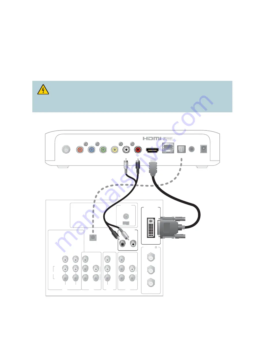
Connecting to an HDTV with a DVI Connector
Cables Used in this Confi guration
• 1 HDMI-to-DVI Cable
or
1 HDMI Cable and 1 HDMI-to-DVI Adapter
• 1 Audio Left/Right Cable (You can also use an optical cable [indicated by the dotted line] instead
of the Audio Left/Right Cable as shown in the diagram, dependent upon your TV’s capabilities.)
Notes:
• The DVI port on the TV must support high-bandwidth digital content protection (HDCP)
• When you connect the HDMI connector to the DVI connector on your HDTV, you need an
HDMI-to-DVI adapter and a separate audio connection
WARNING:
Electric shock hazard! Unplug all electronic devices before connecting or
disconnecting any device cables to the set-top.
Back of Set-Top
L
R
Pr
Pb
Y
CVBS
HDMI
NETWORK
OPTICAL
POWER
F-Con
IR
Back of HDTV
AUDIO
CENTER
CHANNEL IN
ANT (75 )
IN
OUT
ANT-1
HD 2
Y
OUT
ANT-2
P
B
P
R
L
R
VIDEO
L/
MONO
R
L/
MONO
R
AUDIO
IN
ON
OFF
IN
HD 1
S-VIDEO
VIDEO
Y
P
B
P
R
L
R
AUDIO
AUDIO
DVI/HDCP
IN
AUDIO IN
DVI/HDCP
L
R
OPTICAL
INPUT
OR
T16444