8
Product Overview
Cable Side
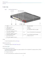
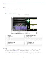
Display Mode Button
The Display Mode Button allows you to choose the mode you want displayed by the port LEDs (items 1-3 in
Figure 4 on page 6
). The
LEDs with green text to the left of the Button indicate the chosen display mode. Each time you press the switch, the mode indicator moves
from SPEED, DUPLX, REDUN, SYNCE, and PoE respectively.
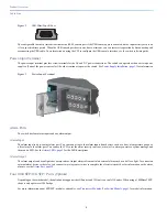
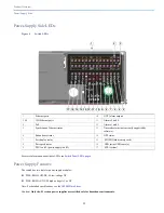
Power-Supply Module LEDs
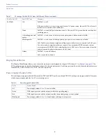
The switch power-supply module LEDs are labeled PSU1 and PSU2 (on the switch) and PSU OK (on the power-supply module). They show
whether power-supply modules 1 and 2 are receiving power.
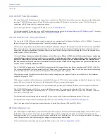
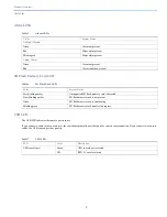
PoE/PoE+
Off
PoE/PoE+ is off.
If the powered device is receiving power from an AC power source, the port LED is off even if
the device is connected to the switch port.
Green
PoE/PoE+ is on and all ports function correctly. The port LED is green when the switch port is
providing power.
Alternating green and
amber
PoE/PoE+ is on but one of the low priority ports power is disconnected or failed.
Blinking amber
PoE/PoE+ is on but one of the high priority ports power is disconnected or failed.
PoE+ faults occur when noncompliant cabling or powered devices are connected to a PoE+ port.
Use only standard-compliant cabling to connect Cisco prestandard IP Phones and wireless
access points or IEEE 802.3af/at-compliant devices to PoE+ ports. You must remove from the
network any cable or device that causes a PoE+ fault.
Amber
PoE/PoE+ is on with failures.
PoE+ is enabled by default.
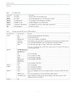
Table 3
Meaning of Switch LED Colors in Different Modes (continued)
Port Mode LED
Port LED Color
Meaning
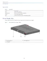
Table 4
Power Supply Module LEDs
Color
System Status
Off
Power-supply module (1 or 2) is not installed.
Green
Valid input is present, and the output is within the operating range.
Red
Valid input is present, and the output is outside the operating range or is not present.
Blinking red
Power-supply module (1 or 2) is installed but valid input is not present.

