

Welcome
The Cisco® Explorer® 9800 Hybrid Video Gateway Series receive and deliver digital
signals, and deliver high-defi nition programming in exceptional picture and audio
quality. Use the simple user interface to access favorite channels and parental
control services. Contact your service provider for information about these and other
available services. Use the instructions in this guide to install the gateway and to
access your program services.
The consumer support website provides news and information about this product.
For more information, please refer to:
http://www.cisco.com/web/consumer/
support/index.html
Safety First
Before using this gateway read the IMPORTANT SAFETY INSTRUCTIONS included
with your gateway.
Avoid Screen Burn-In
Images such as letterbox bars or side bars, bright closed-captioning backgrounds,
station logos, or any other stationary images may cause the TV screen to age unevenly
and cause damage to your TV. Refer to the user guide that came with your TV for more
information about screen burn-in.
Automatic Software Updates
A message appears on the TV screen when the gateway and the M-Card™ module
are receiving software updates. In addition, download information also appears on the
front panel of the gateway during these updates. Wait for the current time to display on
the front panel before continuing. When the time appears, the update is complete.
Performance Tips
If the gateway does not perform as expected, the following tips may help.
No picture
• Verify that the power to your TV is turned on.
• If the gateway is plugged into a wall switch, verify the switch is in the ON position.
(Avoid plugging into an outlet that is controlled by a wall switch.)
• Verify that all cables are properly connected.
• The current channel may not be available in your service package. Try selecting
another channel to see if a picture appears.
No color
• Verify the current TV program is broadcast in color.
• Adjust the TV color controls.
No sound
• If your setup includes a VCR or stereo, verify that you have properly connected
them to the gateway.
• Verify the volume is turned up.
• Verify the mute function is not on.
Record Product Serial Number
If the gateway requires troubleshooting in the future, your service provider may ask
for the set-top serial numbers. The gateway serial number label is on the back panel;
the serial number begins with “STB SN” and is located in the upper left corner of the
bar code.
Use this space to record the set-top serial number:
_______________________________________
Connecting the Gateway to a TV
1. Unplug all electronic devices before connecting the gateway.
2. Connect the gateway and TV. Use the connection diagrams to help you.
3. Connect the gateway to the coaxial cable coming in from the wall.
4. Plug the TV into an AC power source.
5. Plug the gateway’s power cord into an AC power source.
6. For the TV to receive the signal, press the appropriate button on the remote
control to select the audio/video inputs to which you have connected the gateway.
7. Press the
POWER
key on the remote control.
Connecting to an HDTV with an HDMI Connector
Required cables:
• 1 HDMI cable (included)
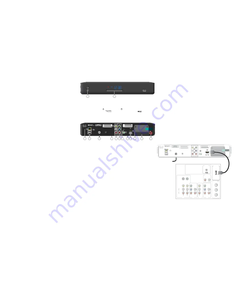
Front Panel
MENU
EXIT
LIST
INFO
VOL-
VOL+
OK
CH-
CH+
9865HDC
T15191
1
2
1
Power
Turns the gateway on and off
2
Display
Displays the selected channel number and time of day. The display
shows the following:
•
Power
(
) • MoCA™ Link ( ) • 480i / 480P
•
Message
(
) • 720i / 720P • Record (
)
• Auto
• 1080i / 1080P
• Sleep mode
Note
: This illustration may vary from the actual product.
Back Panel
USB 2.0
USB 2.0
ETHERNET
CABLE IN
OUTPUT
CUIDADO:
RIESGO DE DESCARGA ELÉCTRICA
NO ABRIR
CAUTION
RISK OF ELECTRIC SHOCK
DO NOT OPEN
LISTED 14H1
VIDEO PRODUCT
CATV CONVERTER
MADE IN MEXICO
Visit www.cisco.com and search
for this model for product information
VIDEO
Y
L
Pb
R
Pr
OPTICAL
AUDIO OUT
IR
eSATA
+12V DC
3A
S T B R F M A C : 0 1 C E A 0 5 D 6 7 9
S T B S N : S A B Q T M N W W
CM VAC: 0011BD73E17D9
VM S/N: VMCPRPSLV
THIS DEVICE IS INTENDED TO BE ATTACHED TO A RECEIVER THAT
IS NOT USED TO RECEIVE OVER-THE-AIR BROADCAST SIGNALS.
CONNECTION OF THIS DEVICE IN ANY OTHER FASHION MAY
CAUSE HARMFUL INTERFERENCE TO RADIO COMMUNICATIONS
AND IS IN VIOLATION OF THE FCC RULES, PART 15.
T15192
2
3
12
11
9
1
4
10
8
7
5
6
1 Ethernet
Connects to external Ethernet equipment approved by your
service
provider
2 USB 2.0
Connects to external USB equipment approved by your service
provider, software controlled
3 Cable In
Connects to a coaxial cable that delivers the signal from your
service
provider
4 Video Out
Connects to the composite input on your TV
5 Audio Out
Connects to RCA cables that send analog audio signals (left and
right) to the stereo inputs on a TV
6 HDTV (YPbPr)
Connects to the component input (YPbPr) on the HDTV
7 IR Remote
Available to be connected to an approved remote IR receiver
Input
(purchased separately)
8 Optical Audio
Connects to an optical cable that sends a digital audio signal
Out
to a surround-sound receiver or other digital audio device input
9 HDMI
Connects an HDMI™ cable to the HDMI input of an HDTV. HDMI
supports both digital audio and video. May be used to connect to a
DVI interface using an HDMI-to-DVI adapter for video and
separate audio connections. Any of the following audio
connections may be used: Audio Out (4) or Optical Audio Out (6)
10 eSATA
Connects to an external Serial ATA (eSATA) hard disk drive for
expanded drive space. A connected eSATA drive is not an archival
device. Ask your service provider for a list of approved hard drive
models for use with the DVR
11 Multi-Stream
Slot for Multi-Stream CableCARD™ module (M-Card), which
CableCARD
decrypts subscription digital channels. This gateway will not
operate correctly without an M-Card module, which is installed by
your service provider
12 AC Power
Connects to the power cord to deliver power to the gateway
Input
Note
: This illustration may vary from the actual product.
Back of Set-Top
T15193
CABLE IN
OUTPUT
CUIDADO: RIESGO DE DESCARGA ELÉCTRICA
NO ABRIR
CAUTION
RISK OF ELECTRIC SHOCK
DO NOT OPEN
LISTED 14H1
VIDEO PRODUCT
CATV CONVERTER
MADE IN MEXICO
VIDEO
Y
L
Pb
R
Pr
OPTICAL
AUDIO OUT
IR
S T B R F M A C : 0 1 C E A 0 5 D 6 7 9
S T B S N : S A B Q T M N W W
USB 2.0
USB 2.0
ETHERNET
eSATA
S T B R F M A C : 0 1 C E A 0 5 D 6 7 9
S T B S N : S A B Q T M N W W
THIS DEVICE IS INTENDED TO BE ATTACHED TO A RECEIVER THAT
IS NOT USED TO RECEIVE OVER-THE-AIR BROADCAST SIGNALS.
CONNECTION OF THIS DEVICE IN ANY OTHER FASHION MAY
CAUSE HARMFUL INTERFERENCE TO RADIO COMMUNICATIONS
AND IS IN VIOLATION OF THE FCC RULES, PART 15.
Visit www.cisco.com and search
for this model for product information
Back of HDTV
HDMI
AUDIO
CENTER
CHANNEL IN
AUDIO IN
DVI/HDCP
ANT (75 )
IN
OUT
L
R
ANT-1
HD 2
Y
OUT
ANT-2
P
B
P
R
L
R
VIDEO
L/
MONO
R
L/
MONO
R
AUDIO
IN
ON
OFF
S-VIDEO
VIDEO
AUDIO
IN
HD 2
Y
P
B
P
R
L
R
AUDIO
Cable Input


