

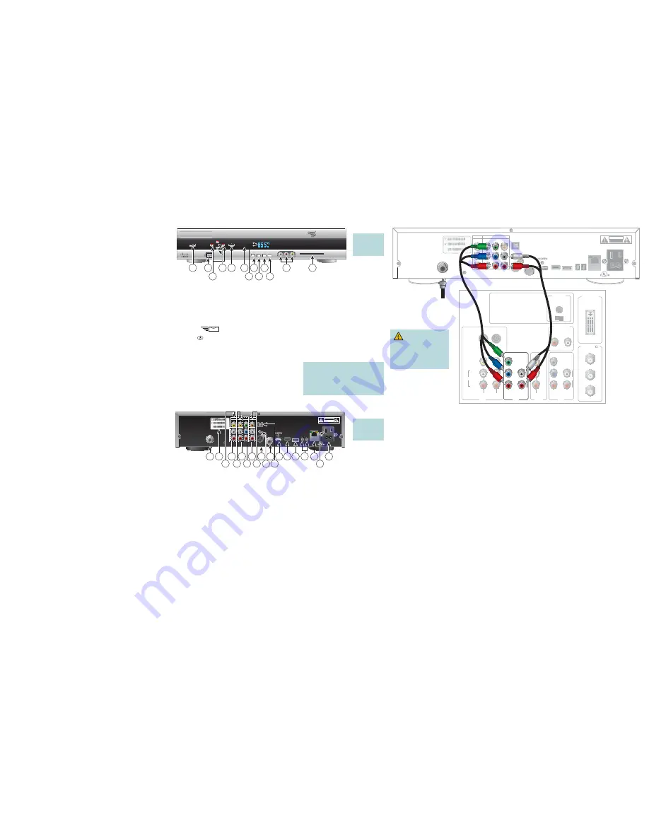
Connecting to an HDTV with Component Input (YPbPr)
1. Connect the DVR to the coaxial cable coming from the wall.
2. Connect the Y (green) connector on the HDTV to the Y (green) connector on the DVR; connect the Pb (blue) connector on the HDTV to the Pb
(blue) connector on the DVR; and connect the Pr (red) connector on the HDTV to the Pr (red) connector on the DVR.
3. Connect the left audio (white) connector on the HDTV to the left audio (white) connector on the DVR, and connect the right audio (red)
connector on the HDTV to the right audio (red) connector on the DVR.
4. Plug the DVR and the HDTV into an AC power source. Do not press the Power key on the DVR yet.
Important
: To potentially protect the DVR from power surge damage, ground (earth) your cable product to provide some protection
against voltage surges and built-up static charges. You may be able to reduce the risk of damage from voltage surges, which can be
caused by lightning storms and power outages, by plugging the DVR into a surge protector.
5. Wait several minutes for the DVR to receive the latest software, programming, and service information. One of the following will appear
on the front panel of the DVR:
• Current time (The update is complete.) • Four dashes (----) (Call your service provider to get the DVR authorized.)
6. To begin watching TV, turn on the HDTV and press
Power
on the front panel of the DVR, or press
Power
on the remote control.
1 Power
Turns the DVR on and off
2 USB
Connects to external USB devices (Reserved for future use)
3 VOL +, VOL -
Increases and decreases the volume
4 CH+, CH -
Scrolls through the channels
5 Select
Accesses your on-screen selection
6 IR Sensor
Receives the infrared signal from the remote control
7 LED Display
Displays the selected channel number and time of day. The LED also displays the following:
• Message
(
)
•
HDTV
• Power (
)
• Output Resolution (1080i, 720p, 480p, or 480i)
• AUTO - Automatically outputs native scan rates that your TV can accept
8 Guide
Accesses the on-screen guide, video-on-demand, or pay-per-view features
9 Info
Displays a description of the selected program. This button is available
from the on-screen guide and while viewing a program
10 Exit
Exits menus, the on-screen guide, and program information
11 List
Displays the Recorded List
12 Video and
Not available on all models. Connects to video and left/right (L/R)
Audio Input
audio outputs from a TV or other device (Not available on 8540HD)
13 Smart Card Slot
Allows Smart Card access
Welcome
The Explorer
®
8540HD™ DVR and 8550HD™ DVR each deliver
high-defi nition programming in exceptional picture and audio
quality. Through the 8540HD and 8550HD you can access
interactive services, such as video-on-demand and pay-per-view
programs. Contact your service provider for information about
these and other available services. Use the instructions in this
guide to install the DVR and to access your program services.
For more information about this product, visit our website:
http://www.cisco.com/web/consumer/support/index.html
Safety First
Before using this DVR read the IMPORTANT SAFETY
INSTRUCTIONS section of this guide.
Watch TV
Press the following remote control keys to access services and
programs:
• Guide–Display the on-screen program guide
• Arrows–Highlight a program in the schedule
• Info–Display program description
• Select–Watch a specifi c program in the guide
Avoid Screen Burn-In
Images such as letterbox bars or side bars, bright closed-
captioning backgrounds, station logos, or any other stationary
images may cause the HDTV screen to age unevenly and cause
damage to your HDTV. Refer to the user’s guide that came with
your HDTV for more information about screen burn-in.
Automatic Software Updates
A message appears on the TV screen when the DVR is receiving
software updates. In addition, download information appears on the
front panel of the DVR during these updates. Wait for the current
time to appear on the front panel before continuing. When the time
appears, the update is complete.
Note:
If you need further assistance, contact your service provider.
Performance Tips
If the DVR does not perform as expected, the following tips may help.
No picture
• Verify that the power to your TV is turned on.
• If the DVR is plugged into a wall switch, verify the switch is in the
ON position. (Avoid plugging into an outlet that is controlled by a
wall switch.)
• Verify that all cables are properly connected.
• The current channel may not be available in your service package.
Try selecting another channel to see if video is available.
No color
• Verify that the HDTV is in HD mode. If necessary, re-run the
HDTV Setup Wizard to select HD mode.
• Verify the current TV program is broadcast in color.
• Adjust the TV color controls.
No sound
• If your setup includes a VCR or stereo, verify that you have
properly connected them to the DVR.
• Verify the volume is turned up.
• Verify the mute function is not on.
Explorer 8550HD Front Panel
Explorer 8550HD Back Panel
1 Cable In
Connects to a coaxial cable that delivers the signal from your service provider
2 Set-Top Box Code Label
Contains set-top serial number and MAC address
3 Archive Video
Connects to a video input of an archive device
4 L-R Audio Archive
Connects to an audio input of an archive device
5 Video 1 (Composite)
Connects to a video input of another device, such as a TV or VCR
6 Audio Out (Left/Right)
Connects to RCA cables that send analog audio signals (left/right) to a stereo receiver or TV with stereo inputs
7 YPbPr
Connects to the component video input (YPbPr) on an HDTV. Do not use these cables if you are using the
HDMI
connection
8 Out 2 (Secondary
Connects to either a VCR or to another set of inputs (composite) on your TV
Audio Out)
9 Digital Audio Out
Connects to an RCA cable that sends a digital audio signal to a surround-sound receiver or other digital audio device
10 S-Video Out
Connects to S-Video input of a standard TV or VCR
11 IR
Connector reserved for future use
12 Optical Audio Out
Connects to an optical cable that sends a digital audio signal to a surround-sound receiver or other digital
audio
device
13 Cable Out
Connects to a coaxial cable that sends analog audio and video signals to a TV or VCR. These signals are
SDTV video and stereo audio
14 HDMI
Connects an HDMI™ cable to the HDMI input of an HDTV. HDMI supports both digital audio and video. May be used
to connect to a DVI interface using an HDMI-to-DVI adapter for video and separate audio connections. Any of the
following audio connections may be used: Digital Audio Out (9); Audio Out: Left, Right (6); or Optical Audio Out (12)
15 USB 2.0
Connects to external USB device (Reserved for future use)
16 eSATA
Connects to an external Serial ATA (eSATA) hard disk drive for expanded drive space. A connected eSATA drive is
not an archival device. Ask your service provider for a list of approved hard drive models for use with the DVR
17 1394
Connects to display devices equipped with a 1394 input
18 Ethernet
Connects to an Ethernet-equipped device (Reserved for future use)
19 AC Outlet
Connects to the AC power cord from another device, such as a TV
20 AC Power Input
Connects to the power cord to deliver power to the set-top
Safety and Performance Tips
• Keep the top of the DVR free of all objects
and electronic devices, including your TV.
• Always set the DVR on its feet, never on
its side.
Connection Example
Note
: This
illustration may
vary from the
actual product.
WARNING:
Electric shock hazard!
Unplug all electronic
devices before connecting
or disconnecting any device
cables to the DVR.
POWER
SELECT
VOL+
VOL-
CH+
CH-
LIST
EXIT
INFO
GUIDE
L AUDIO IN R VIDEO IN
EXPLORER
®
8550HD
™
T15644
8
2
9
10
13
12
11
1
5
6
4
3
7
THIS DEVICE IS INTENDED TO BE ATTACHED TO A
RECEIVER THAT IS NOT USED TO RECEIVE OVER-THE-AIR
BROADCAST SIGNALS. CONNECTION OF THIS DEVICE
IN ANY OTHER FASHION MAY CAUSE HARMFUL
INTERFERENCE TO RADIO COMMUNICATIONS
AND IS IN VIOLATION OF THE FCC RULES, PART 15.
CABLE OUT
S-VIDEO
OUT
USB 2.0
120VAC
60Hz 80W
120 VAC
60Hz 4.2A
500W
OPTICAL
AUDIO
OUT
VIDEO
ARCHIVE
OUT 1
L
R
VIDEO
L
R
Pb
Y
Pr
DIGITAL
AUDIO
L
R
IR
1394
AVIS: RISQUE DE CHOC
ELECTRIQUE NE PAS OUVRIR
CAUTION
RISK OF ELECTRIC SHOCK
DO NOT OPEN
1394
eSATA
CABLE
IN
SCIENTIFIC-ATLANTA, INC.
CATV CONVERTER
MADE IN MEXICO
LISTED 14H1
VIDEO PRODUCT
eCM MAC: 001AC3F4F757
STB RF MAC: 001AC3F$F756
STB SN: SABPQBQGD
T
1
5645
1
2
4
3
6
8
19
11
20
18
5
9
13
7
10 12 14 15 16 17
Note
: This
illustration may
vary from the
actual product.
T15646
eCM MAC: 001AC3F4F757
STB RF MAC: 001AC3F$F756
STB SN: SABPQBQGD
THIS DEVICE IS INTENDED TO BE ATTACHED TO A
RECEIVER THAT IS NOT USED TO RECEIVE OVER-THE-AIR
BROADCAST SIGNALS. CONNECTION OF THIS DEVICE
IN ANY OTHER FASHION MAY CAUSE HARMFUL
INTERFERENCE TO RADIO COMMUNICATIONS
AND IS IN VIOLATION OF THE FCC RULES, PART 15.
CABLE
IN
CABLE OUT
S-VIDEO
OUT
USB 2.0
120VAC
60Hz 80W
120 VAC
60Hz 4.2A
500W
OPTICAL
AUDIO
OUT
VIDEO
ARCHIVE
OUT 1
L
R
VIDEO
L
R
Pb
Y
Pr
DIGITAL
AUDIO
L
R
IR
1394
AVIS: RISQUE DE CHOC
ELECTRIQUE NE PAS OUVRIR
CAUTION
RISK OF ELECTRIC SHOCK
DO NOT OPEN
1394
eSATA
SCIENTIFIC-ATLANTA, INC.
CATV CONVERTER
MADE IN MEXICO
LISTED 14H1
VIDEO PRODUCT
Back of
HDTV
DVI/HDCP
IN
AUDIO
CENTER
CHANNEL IN
AUDIO IN
DVI/HDCP
ANT (75 )
IN
OUT
L
R
ANT-1
HD 2
Y
OUT
ANT-2
P
B
P
R
L
R
VIDEO
L/
MONO
R
L/
MONO
R
AUDIO
IN
ON
OFF
IN
HD 1
S-VIDEO
VIDEO
Y
P
B
P
R
L
R
AUDIO
AUDIO
Cable
Input