background image

10

1

14

3

4

5

7

8

19

20

6

18

17

2

9

21
22

23
24

10

11

13

25

26

12

15
16

27
28

T13403

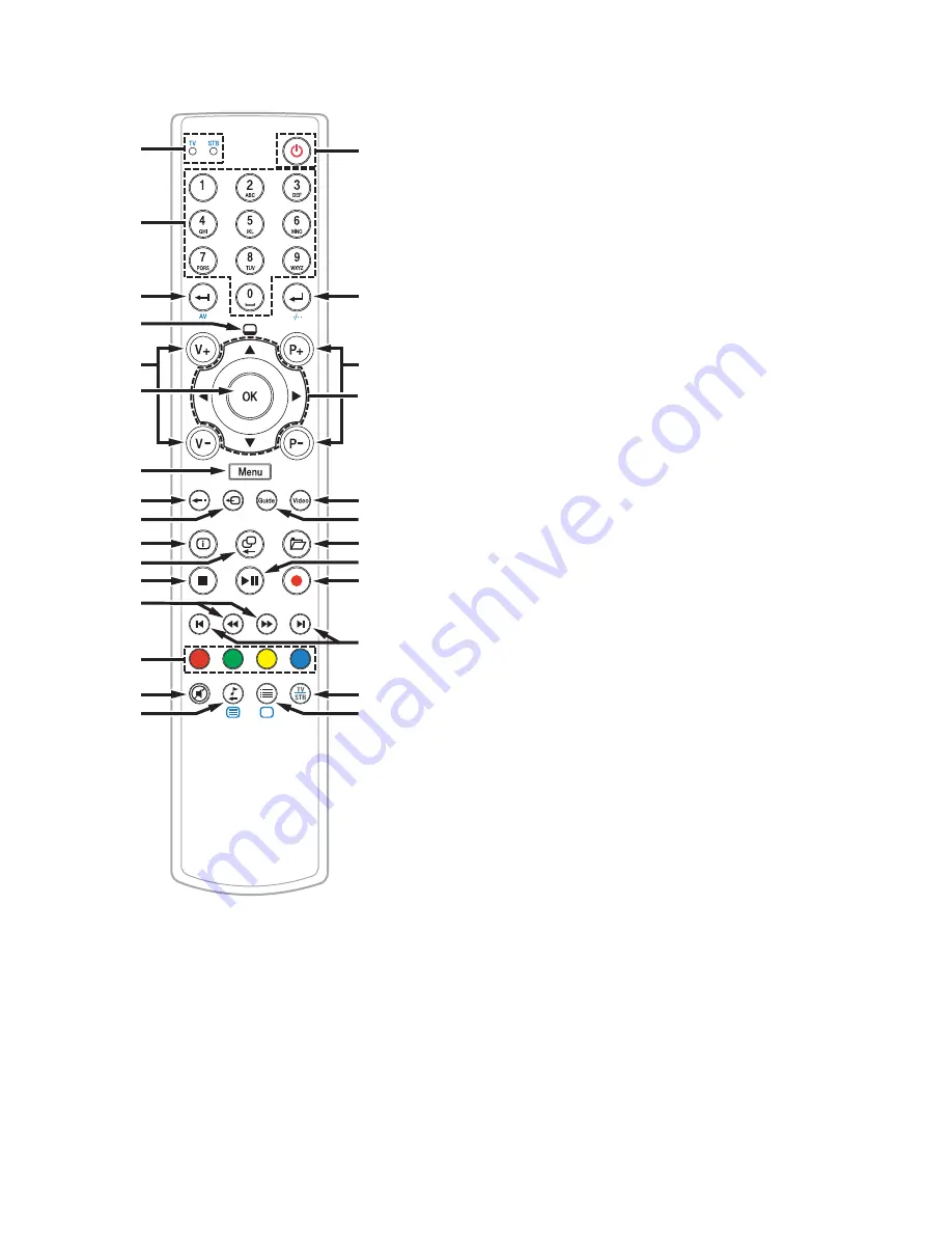
Remote Control Features


1

  Indicates if the remote is controlling the set-top 

(STB) or the TV.  

Operation mode display 

STB: Illuminates when the IP set-top is controlled 
by remote
TV: Illuminates when the TV is controlled by 
remote


2

  STB mode: Direct selection of channels; Text 

entry in input fi elds
TV mode: Direct selection of individual channels


STB mode: Delete entry
TV mode: Switch AV-input or switch to an 
external device


4

  Displays the preview window


5

  Volume control – Adjusts sound to be louder 

or quieter


6

 Confi rms your selection in a menu


7

  Displays the start menu


8

  Returns to the last displayed page


9

  Switches to TV picture


10

  Shows information about the current program


11

  Switches to previously selected channel or 

changes the screen display


12

  Stops recording or playback


13

  Fast forward or rewind spooling


14

 Multi-function 

buttons


15

  Turns the sound on and off


16

  STB mode: Starts radio channels (for future use)

TV mode: Starts Videotext


17


Power

STB mode: Switches your set-top on and off
TV mode: Switches your TV on and off

18 

  STB mode: Confi rms entry

TV mode: Allows 2-digit channel numbers to 
be entered


19

  Switching the channels and programs


20

  Navigates through menus


21

  Tunes to video-on-demand programming


22

  Activates the electronic program guide (EPG)


23

  Accesses the VIDEO RECORDER menu


24

  Pauses a video-on-demand program and 

(when pressed again) recommences the 
program display with a time delay


25

  Records the current TV program directly; 

programs the current TV program for 
recording (not currently supported on this 
set-top)


26

  Skips forward or backward


27

  Switches from STB mode to TV mode and back


28

  STB mode: Options – Switches to list of 

options
TV mode: Switches from Teletext to TV-
channel

Summary of Contents for CIS2000

Page 1: ...CIS2000 IP Set Top Quick Reference Guide REC SIG HD ...

Page 2: ...ided to call the system installer s attention to Article 800 93 and Article 800 100 of the NEC or Canadian Electrical Code Part 1 which provides guidelines for proper grounding of the coaxial cable shield This symbol is intended to alert you that uninsulated voltage within this product may have sufficient magnitude to cause electric shock Therefore it is dangerous to make any kind of contact with ...

Page 3: ...CTIONS 2 Safety First 4 Identify Your Set Top 4 Front Panel Features 5 Back Panel Connectors 6 Preparation and Installation Overview 7 Installation and Power On 8 Inserting Batteries into the Remote Control 9 Remote Control Features 10 ...

Page 4: ...Heed All Warnings Follow All Instructions Power Source Warning A label on this product indicates the correct power source for this product Operate this product only from an electrical outlet with the voltage and frequency indicated on the product label If you are uncertain of the type of power supply to your home or business consult your service provider or your local power company The AC inlet on...

Page 5: ...amaged liquid has been spilled or objects have fallen into the apparatus the apparatus has been exposed to rain or moisture does not operate normally or has been dropped Check Product Safety Upon completion of any service or repairs to this product the service technician must perform safety checks to determine that this product is in proper operating condition Protect the Product when Moving It Al...

Page 6: ...der may ask for the serial number or the MAC address of the set top if your system requires troubleshooting in the future Look for the serial number and the MAC address on the bottom of the set top Write the serial number here ____________________________________________ Write the MAC address here ____________________________________________ ...

Page 7: ...de The LED is red 2 SIG Indicates that a network signal is being received The LED is yellow 3 HD Indicates that a high definition HD program is in progress The LED is blue 4 IR Sensor Receives the infrared signal from the remote control 5 On Standby Switches between On and Standby modes The power status includes a dual colored ring The ring is green when power is on the ring is red when in standby...

Page 8: ...VCR or stereo receiver 5 Composite Video Connects to a TV VCR or monitor with composite video input output 6 Reset button Restarts the IP set top 7 Digital Audio Connects with an optical cable to send a digital audio signal to connector a surround sound receiver or other digital audio device 8 IR Extender output Connects to an IR extender 9 Power supply input Connects with the supplied external po...

Page 9: ...ustomer Services department Note The package you receive may contain additional cables or devices Installation and location The CIS2000 is designed for operation in closed dry rooms with a temperature range from 5º to 40ºC Each set top should have at least 2 inches of open space above it and on each of its sides Caution Never expose the equipment to sources of heat or the direct impact of sunlight...

Page 10: ...a CAT5 CAT5e or CAT6 Ethernet cable 2 Connect the IP set top to a TV monitor or HDMI equipped device using an HDMI to HDMI cable 3 Connect the IP set top to a power supply Back of HDTV HDMI AUDIO CENTER CHANNEL IN AUDIO IN DVI HDCP ANT 75 IN OUT L R ANT 1 HD 2 Y OUT ANT 2 PB PR L R VIDEO L MONO R L MONO R AUDIO IN ON OFF IN HD 1 S VIDEO VIDEO Y PB PR L R AUDIO AUDIO Analog Video Composite R L DC I...

Page 11: ... back of the remote control push the tab down and pull the battery cover away from the device 2 Insert the batteries in a single row into the compartment Pay attention to the polarity of the batteries The correct position is indicated inside the battery compartment 3 Insert the battery cover edge opposite tab and push it toward the remote control until the tab locks into place T13402 ...

Page 12: ...d channel or changes the screen display 12 Stops recording or playback 13 Fast forward or rewind spooling 14 Multi function buttons 15 Turns the sound on and off 16 STB mode Starts radio channels for future use TV mode Starts Videotext 17 Power STB mode Switches your set top on and off TV mode Switches your TV on and off 18 STB mode Confirms entry TV mode Allows 2 digit channel numbers to be enter...

Page 13: ...11 ...

Page 14: ...nd High Definition Multimedia Interface are trademarks or registered trademarks of HDMI Licensing LLC Other third party trademarks mentioned in this document are the property of their respective owners The use of the word partner does note imply a partnership relationship between Cisco and any other company 1110R Product and service availability is subject to change without notice LVFR DQG RU LWV ...

Reviews: