background image

3.Important Notes 

                                                                                                                                                                                7 


3. Important Notes 


3.1.  Notes on Safety 

This chapter provides safety instructions which you must observe when handling your storage subsystem. 

The device complies with the relevant safety regulations for data processing equipment. 

The following safety instructions can also be found in the manual 

entitled “Safety notes and other 

important information”. Please also read the notes in the operating manual for the attached system. 

If you have any questions on setting up and operating the device in your particular environment, please 

contact your sales outlet or one of our Service Desks. 


ATTENTION!


  The activities described in this manual may only be performed by specialist technical personnel. 

Equipment repairs must only be performed by service staff. Any unauthorized opening or improper 

repairs could endanger the user (through  electric shock, energy  hazard, fire  hazard) or  damage 

the  equipment.  Please  note  that  any  unauthorized  opening  of  the  device  will  result  in  the 

invalidation of the warranty and exclusion from all liability. 

  Transport the device only in its original packaging or in packaging which protects it from knocks 

and jolts. 

  If the device is brought in from a cold environment, condensation may form both inside and on the 

outside  of  the  machine.  Before  operating  the  device,  wait  until  it  is  dry  and  has  reached 

approximately the same temperature as the installation site. Failure to observe these guidelines 

can lead to material damage of the device. 

  Check  that  the  rated  voltage  specified  on  the  device's  ID  plate  is  the  same  as  the  local  mains 

voltage. 

  Only connect the device to a properly grounded wall outlet (the device is fitted with a tested and 

approved power cable). 


Summary of Contents for C880 Series

Page 1: ...Service Supplement Cisco C880 M4 Storage Subsystem Service Supplement October 2014 ...

Page 2: ...VE NAMED SUPPLIERS DISCLAIM ALL WARRANTIES EXPRESSED OR IMPLIED INCLUDING WITHOUT LIMITATION THOSE OF MERCHANTABILITY FITNESS FOR A PARTICULAR PURPOSE AND NONINFRINGEMENT OR ARISING FROM A COURSE OF DEALING USAGE OR TRADE PRACTICE IN NO EVENT SHALL CISCO OR ITS SUPPLIERS BE LIABLE FOR ANY INDIRECT SPECIAL CONSEQUENTIAL OR INCIDENTAL DAMAGES INCLUDING WITHOUT LIMITATION LOST PROFITS OR LOSS OR DAMA...

Page 3: ... 7 3 1 Notes on Safety 7 3 2 ESD Label 9 3 3 CE Conformity 10 3 4 RFI Suppression 10 3 5 Notes on Mounting the Rack 10 3 6 Environmental Protection 11 4 Replacing Components 12 4 1 Preparation 12 4 2 Replacing the SAS Expander Module 13 4 3 Replacing the LED Display 14 4 4 Replacing the Backplane 17 5 Cable Overview 19 Abbreviations 20 Figure 26 Table 27 ...

Page 4: ...formed by specialist personnel with technical training The installation and removal of the hot plug components is described in the operating manual supplied with the storage subsystem Information Activity Manual Features and technical data of the storage subsystem Installation and activation including External connections to the storage subsystem Operation Configuration of the storage subsystem In...

Page 5: ...s and terms that need to be emphasized indicates an activity that must be performed ATTENTION indicates that if you ignore the information given at this point your health the correct functioning of your system or the security of your data may be at risk indicates supplementary information remarks and tips Table 2 Notational conventions ...

Page 6: ...necessary You will definitely need the operating manual for the storage subsystem Shut down the server connected to the storage subsystem correctly see the operating manual for the relevant server Pull out the power plugs of your storage subsystem and if necessary also disconnect the cables of the expander module as described in the chapter Replacing Components on page 12 Replace the defective com...

Page 7: ...by service staff Any unauthorized opening or improper repairs could endanger the user through electric shock energy hazard fire hazard or damage the equipment Please note that any unauthorized opening of the device will result in the invalidation of the warranty and exclusion from all liability Transport the device only in its original packaging or in packaging which protects it from knocks and jo...

Page 8: ...ust use a separate fused socket for each cabinet Always connect the server and the directly connected external storage subsystems to the same power supply distributor Otherwise you run the risk of losing data if for example the central unit is still running but the storage subsystem has failed during a power cut Make sure that no objects such as bracelets or paper clips fall into or liquids spill ...

Page 9: ...of electrostatic charge Pull out the power plug before installing or uninstalling modules containing electrostatic sensitive components Touch modules containing electrostatic sensitive components only at the edges Do not touch any connectors or conduction paths on a module containing electrostatic sensitive components While installing modules wear a suitable grounding strap that connects you to th...

Page 10: ... for Telecommunications BZT This is Class A equipment This equipment may cause harmful inter ference in residential areas In this case the user may be required to take appropriate measures and bear the costs resulting from these measures 3 5 Notes on Mounting the Rack For safety reasons at least two people are required to install the storage subsystem because of its weight and size When connecting...

Page 11: ...rts Avoid sticking your own labels on plastic housing parts whenever possible as this makes recycling more difficult Take back recycling and disposal The device must not be disposed of together with regular household refuse This device is labeled according to European directive 2002 96 EC on Waste from Electrical and Electronic Equipment WEEE This directive sets the framework for EC wide take back...

Page 12: ...e 7 4 1 Preparation To replace components which are not hot pluggable proceed as follows Shut down the server connected to the storage subsystem wait until the server and the storage subsystem are switched off Unplug the two power plugs of the storage subsystem from the mains Disconnect the SAS cable s from the SAS expander module after keeping a record for the correct reconnection ...

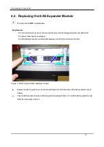
Page 13: ...power cables have been uplugged The SAS cable s have been removed after keeping a record for the correct reconnection Figure 2 Removing the SAS expander module Release the latch of ejector lever on both sides with fingers of both hands and pull the SAS expander unit out halfway Take the SAS expander module out of the bay while supporting its bottom To install the SAS expander module follow the abo...

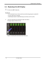
Page 14: ...hut down and the server and the storage subsystem are switched off The power cables have been unplugged The SAS cable s have been removed after keeping a record for the correct reconnection Loosen the knurled thumb screw which fastens the bezel on the left side of the storage subsystem and remove the bezel Figure 3 Loosening the knurled thumb screw of the bezel ...

Page 15: ...he flexible flat cable FFC be careful not to damage or break the lever the connector or the FFC Lift up the lever of the flexible flat cable connector to the left 1 Remove the connector carefully from the panel 2 Undo the two screws 3 Remove the metal plate the printed board and the foil behind it 3 3 1 2 ...

Page 16: ...4 3Replacing the LED Display 16 Operating Manual Figure 5 Panel parts To install the LED displayfollow the above steps in reverse ...

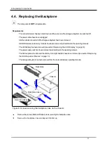
Page 17: ...LED display has been removed see section Replacing the LED Display on page 19 The power supply units have been removed as described in the operating manual The SAS expander module and the dummy blind right beside it have been removed see section Replacing the SAS Expander Module on page 13 The storage subsystem has been removed from the rack cabinet see operating manual Figure 6 Screws securing th...

Page 18: ... flexible flat cable connector FFC connecting the backplane lift up the lever and disconnect the FFC Figure 8 Screws securing the backplane Remove the screws securing the backplane Replace the backplane with a new replacement one To reassemble the storage subsystem follow the above procedure basically in reverse ...

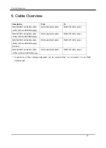
Page 19: ...e 4 0m with two SFF8088 plugs SAS expander module RAID Ctrl of the server External SAS connection cable 6 0m with two SFF8088 plugs planned SAS expander module RAID Ctrl of the server External SAS connection cable 0 75m with two SFF8088 plugs SAS expander module RAID Ctrl of the server A maximum of three storage subsystem can be daisy chained in a connection to one RAID controller port ...

Page 20: ...lternating Current ACPI Advanced Configuration and Power Interface ANSI American National Standard Institute ASR R Automatic Server Reconfiguration and Restart ATA Advanced Technology Attachment BBU Battery Backup Unit BIOS Basic Input Output System BMC Baseboard Management Controller CC Cache Coherency CHS Cylinder Head Sector CMOS Complementary Metal Oxide Semiconductor COM Communication CPU Cen...

Page 21: ...romagnetic Compatibility EMI Electromagnetic interference EMP Emergency Management Port EMRL Embedded RAID Logic ESD Electrostatic Sensitive Devices Electro Static Discharge EVRD Enterprise VRD FPC Front Panel Controller FRU Field Replaceable Unit FSB Front Side Bus GUI Graphical User Interface HBA Host Bus Adapter HDD Hard Disk Drive HPC Hot plug Controller HSC Hot swap Controller I2 C ...

Page 22: ...rated Mirroring Enhanced IPMB Intelligent Platform Management Bus IPMI Intelligent Platform Management Interface iRMC integrated Remote Management Controller IRQ Interrupt Request Line LAN Local Area Network LBA Logical Block Address LCD Liquid Crystal Display LUN Logical Unit Number LVD Low Voltage Differential SAS MMF Multi Mode Fiber MRL Manual Retention Latch NMI Non Maskable Interrupt NVRAM N...

Page 23: ...utput PLD Programmable Logic Device POST Power On Self Test PS U Power Supply Unit RAID Redundant Arrays of Independent Disks RoHS Restriction of the Use of Certain Hazardous Substances Waste from Electric and Electronic Equipment EU guideline RoMB RAID on Motherboard RSB RemoteView Service Board RST ReSeT RTC Real Time Clock RTDS Remote Test and Diagnostics System SAF TE SCSI Accessed Fault Toler...

Page 24: ...Access Memory SEL System Event Log SHDG Server Hardware Design Guide SMI System Management Interrupt SMM Server Management Mode SMP Symmetrical Multi Processing SSD Solid State Disk SSU System Setup Utility SVGA Super Video Graphics Adapter UHCI Unified Host Controller Interface USB Universal Serial Bus WEEE Waste from Electric and Electronic Equipment EU directive WfM Wired for Management WOL Wak...

Page 25: ...0 Abbreviations 25 ...

Page 26: ...er module 13 Figure 3 Loosening the knurled thumb screw of the bezel 14 Figure 4 Removing the panel behind the bezel 15 Figure 5 Panel parts 16 Figure 6 Screws securing the backplane case on the chassis 17 Figure 7 Removing installing the FFC from to the backplane 18 Figure 8 Screws securing the backplane 18 ...

Page 27: ...0 Table 27 Table Table 1 Overview of the documentation 4 Table 2 Notational conventions 5 ...

Reviews: