Cisco AS5800 Manual Download Page 9

The ports labeled "Network Clock," "10BaseT," "Dial Shelf
Interconnect," "Console," and "Alarms" are safety extra­low voltage
(SELV) circuits. SELV circuits should only be connected to other SELV
circuits. Because the E1/T1 circuits are treated like telephone­network
voltage, avoid connecting the SELV circuit to the telephone network
voltage (TNV) circuits.

CT1 Trunk Card Cables and Pinouts

One interface cables is available from Cisco Systems for connecting
the CT1 card ports; the cable is described in .

Table 5

Cable Description

Product Number

RJ­45 to Bare, 100­ohm

CAB­T1­RJ45BARE

CT1 Interface Cables

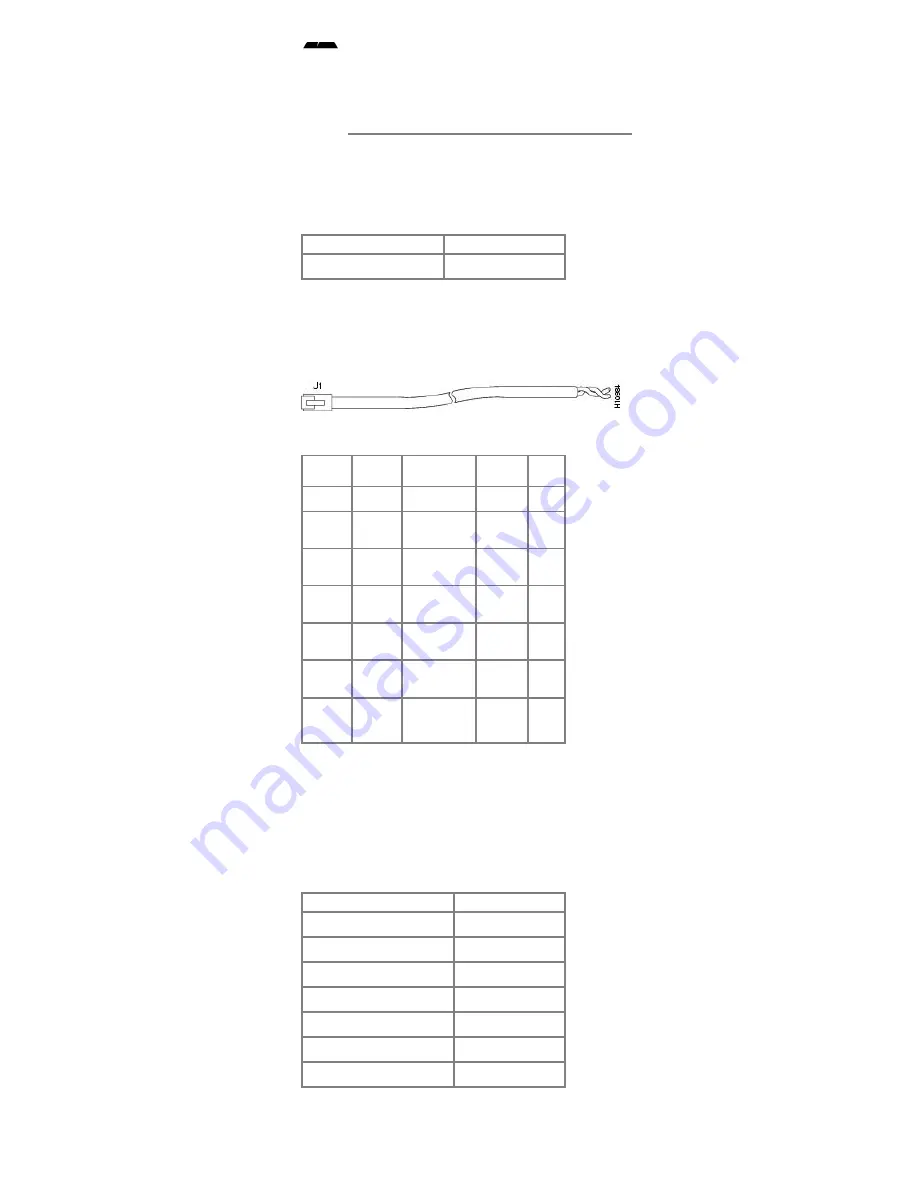
The shows the CT1 interface cable, and describes the pinouts for the
CT1 interface cable.

Figure 7 RJ­45­to­Bare Wire Interface Cable

Table 6

RJ­45
Pin

Signal

Description

Direction Bare

Shield

Ground

Braid


J1­1

RX Tip

Twisted Pair
#1

      <—

WIRE­
1

J1­2

RX Ring Twisted Pair

#1

      <—

WIRE­
2

J1­3

RX
Shield


J1­4

TX Tip

Twisted Pair
#2

      —>

WIRE­
3

J1­5

TX Ring

Twisted Pair
#2

      —>

WIRE­
4

J1­6

TX
Shield


RJ­45­to­Bare Cable Pinouts

CE1 Trunk Card Cables and Pinouts

Seven interface cables are available from Cisco Systems for
connecting the CE1 card ports; these cables and their product
numbers are listed in .

Table 7

Cable Description

Product Number

RJ­45 to RJ­45, 120­ohm

CAB­E1­RJ45RJ45

RJ­45 to DB­15, 120­ohm

CAB­E1­RJ45DB15

RJ­45 to DB­15 Null, 120­ohm CAB­E1­RJ45DB15N

RJ­45 to BNC, 75­ohm

CAB­E1­RJ45BNC

RJ­45 to Twinax, 75­ohm

CAB­E1­RJ45TWIN

RJ­45 to RJ­45 TE, 120­ohm

CAB­E1­RJ45TE

RJ­45 to RJ­45 NT, 120­ohm

CAB­E1­RJ45NT

CE1 Interface Cables

The following figures and tables illustrate and describe the pinouts for
each CE1 interface cable:

Summary of Contents for AS5800

Page 1: ... CE1 ingress interfaces that provide a synchronous telecommunication interface in both North American and international environments The CT1 or CE1 trunk card is installed in the Cisco 5814 dial shelf in the Cisco AS5800 Universal Access Server This document explains how to remove and replace a CT1 or CE1 trunk card in the Cisco 5814 dial shelf chassis It also includes steps for verifying and trou...

Page 2: ...Feedback on the toolbar and then select Documentation After you complete the form click Submit to send it to Cisco We appreciate your comments For additional Cisco IOS software information refer to the following modular configuration and modular command reference publications as appropriate for your configuration Configuration Fundamentals Configuration Guide Configuration Fundamentals Command Ref...

Page 3: ...cessing The router shelf also houses the main system software images shows a front view of a fully configured Cisco AS5800 Universal Access Server and shows a rear view Figure 1 Cisco AS5800 Universal Access Server Front View Figure 2 Cisco AS5800 Universal Access Server Rear View ...

Page 4: ...card provides physical termination for up to 12 T1 Primary Rate Interface PRI lines includes channel service units CSUs and connects directly to the telco network Demultiplex DS0s A framer removes framing and embedded signaling bits or inserts them depending on the direction of the flow and the framer CPU sends the data stream to onboard time division multiplexing TDM resources which break out eac...

Page 5: ...locks per trunk card For example if you install three trunk cards you can configure up to six clocks While two trunk cards are sufficient to give full coverage to ten modem cards you can have up to six trunk cards seated in slots 0 through 5 for a maximum selection of twelve clocks If you configure fewer than two clocks on a trunk card and all other configured clocks fail the clock selection will ...

Page 6: ...and you have completed a card level software busyout Indicates the card is ready to be removed E1FR E1 Framing Green E1 trunk card only Lights when the card is configured for E1 framing T1FR T1 Framing Green T1 trunk card only Lights when the card is configured for T1 framing HCPU Host CPU OK Green Lights when the host CPU is operating normally FCPU Framer CPU OK Green Lights when the framer CPU i...

Page 7: ...o detect T1 or E1 errors The 4 character LCD indicates which of the 12 T1 or E1 lines are to be monitored or inspected using the bantam jacks To enable the bantam jacks for port monitoring follow these steps Step 1 Push and quickly release the pushbutton labeled monitor below the LCD to toggle to the port number you want to display You must release the button within two seconds to advance through ...

Page 8: ...E1 Trunk Card Port Pinout The CT1 trunk card receives and transmits 1 544 Mbps signals through a 100 ohm cable using common RJ 45 connectors Use a straight through RJ 45 to RJ 45 cable to connect the T1 lines to an RJ 45 receptacle The CE1 trunk card receives and transmits 2 048 Mbps CE1 signals through either 120 ohm or 75 ohm coaxial cable All CE1 interface cables use common RJ 45 connectors on ...

Page 9: ...re Interface Cable Table 6 RJ 45 Pin Signal Description Direction Bare Shield Ground Braid J1 1 RX Tip Twisted Pair 1 WIRE 1 J1 2 RX Ring Twisted Pair 1 WIRE 2 J1 3 RX Shield J1 4 TX Tip Twisted Pair 2 WIRE 3 J1 5 TX Ring Twisted Pair 2 WIRE 4 J1 6 TX Shield RJ 45 to Bare Cable Pinouts CE1 Trunk Card Cables and Pinouts Seven interface cables are available from Cisco Systems for connecting the CE1 ...

Page 10: ...ssover Figure 9 RJ 45 to DB 15 Interface Cable Table 9 RJ 45 Pin Signal Description Direction DB 15 Pin Shield Ground Shell Braid Shell J1 1 RX Tip Twisted Pair 1 J2 3 J1 2 RX Ring Twisted Pair 1 J2 11 J1 3 RX Shield Twisted Pair 3 J2 4 J1 4 TX Tip Twisted Pair 2 J2 1 J1 5 TX Ring Twisted Pair 2 J2 9 J1 6 TX Shield Twisted Pair 4 J2 2 RJ 45 to DB 15 Cable Pinouts Table 10 RJ 45 Pin Signal Descript...

Page 11: ...ir 1 RX Shield J1 3 RX Shield Twisted Pair 3 RX Shield J1 4 TX Tip Twisted Pair 2 TX Tip J1 5 TX Ring Twisted Pair 2 TX Shield J1 6 TX Shield Twisted Pair 4 TX Shield RJ 45 to BNC Cable Pinouts Figure 11 RJ 45 to Twinax Interface Cable for 75 Ohm Unbalanced Connections Table 12 RJ 45 Pin Signal Description Direction Twinax Pin Shield Ground Shell RX TX Shields J1 1 RX Tip Twisted Pair 1 RX 1 J1 2 ...

Page 12: ...ted Pair 3 TX Shield J2 6 J1 4 TX Tip Twisted Pair 2 RX Tip J2 1 J1 5 TX Ring Twisted Pair 2 RX Ring J2 2 J1 6 TX Shield Twisted Pair 4 RX Shield J2 3 RJ 45 to RJ 45 NT Cable Pinouts Crossover Warning The ports labeled Network Clock 10BaseT Dial Shelf Interconnect Console and Alarms are safety extra low voltage SELV circuits SELV circuits should only be connected to other SELV circuits Because the...

Page 13: ...er or telephone wiring Locate the emergency power off switch for the room in which you are working before beginning any procedures requiring access to the chassis interior Never work alone when potentially hazardous conditions exist Never assume that power has been disconnected from a circuit always check Never perform any action that creates a potential hazard to people or makes the equipment uns...

Page 14: ...merkki merkitsee vaaraa Olet tilanteessa joka voi johtaa ruumiinvammaan Ennen kuin työskentelet minkään laitteiston parissa ota selvää sähkökytkentöihin liittyvistä vaaroista ja tavanomaisista onnettomuuksien ehkäisykeinoista Tässä julkaisussa esiintyvien varoitusten käännökset löydät laitteen mukana olevasta Regulatory Compliance and Safety Information kirjasesta määräysten noudattaminen ja tieto...

Page 15: ...er denna anordning Removing and Replacing a Trunk Card Depending on your configuration requirements you might need to replace existing trunk cards or install new trunk cards in your Cisco 5814 dial shelf Because the system is designed to recognize trunk cards only when they are installed in the first six slots you must install trunk cards in slots numbered slots 0 through 5 on the dial shelf backp...

Page 16: ...onnect the telephone network cables to avoid contact with telephone network voltages Caution Trunk cards weigh 8 lb 3 6 kg each Use two hands when removing or replacing a trunk card To remove a trunk card from the Cisco 5814 dial shelf follow these steps Step 1 Note the slot in which the trunk card is installed If you decide to install the new trunk card in the same slot this will hasten the insta...

Page 17: ...ne hand Place your other hand under the trunk card to balance the weight of the card as you pull it out of the slot See Step 9 Pull the trunk card straight out of the slot Avoid touching the circuitry or any connector pins Figure 14 Removing and Replacing the CT1 or CE1 Trunk Card Step 10 Place the removed trunk card on an antistatic mat or foam pad until you are ready to reinstall it in the chass...

Page 18: ...ding Caution Always tighten the panel fasteners on trunk cards These fasteners prevent accidental removal and provide proper grounding for the system Step 6 Repeat Step 2 through Step 5 for any other trunk cards you want to install Caution To avoid erroneous failure messages remove or insert only one trunk card at a time Also after inserting or removing a trunk card allow at least 15 seconds befor...

Page 19: ...and is required for CE1 trunk cards If you change the cable length when installing and cabling a new trunk card you need to specify cable length in your software configuration The cablelength command is designed to recognize two basic fixed settings Cable Length Short Cable Length Long Cable Length Short The following cable length short configurations define the length range in feet between your N...

Page 20: ...s to AS5800 1 2 A S 5 8 0 0 1 c o n f i g u r et e r m i n a l E n t e rc o n f i g u r a t i o nc o m m a n d s o n ep e rl i n e E n d w i t hC N T L Z A S 5 8 0 0 1 c o n f i g Enter global configuration mode by typing the configure command The example is using the terminal configuration option You are in global configuration mode when the prompt changes to AS5800 1 config 3 A S 5 8 0 0 1 c o n...

Page 21: ...ing the CT1 and CE1 Trunk Card The Cisco 5814 dial shelf only recognizes CT1 and CE1 trunk cards in slots 0 through 5 within the dial shelf chassis therefore you must install trunk cards only in the first six slots If you are replacing a trunk card in the same slot as the one you just removed the system automatically recognizes the previous system configuration and no other configuration is needed...

Page 22: ...tacts Feedback Help Site Map Terms Conditions Privacy Statement Cookie Policy Trademarks Information For Small Business Midsize Business Service Provider Executives Home Linksys Contacts Contact Cisco Find a Partner News Alerts Newsroom Blogs Field Notices Security Advisories Technology Trends Cloud IPv6 Mobility Open Network Environment Trustworthy Systems Support Downloads Documentation Communit...

Reviews: