background image

Replacing the Power Supply in Cisco AS5200 Universal Access Servers  7

Removing the Power Supply

Removing the Power Supply

Take these steps:

Step 1

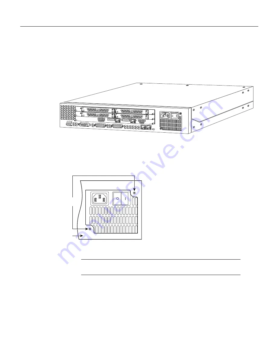
Place the access server so that the rear panel is facing you.

Figure 4

Cisco AS5200 Access Server Rear Panel

Step 2

Remove the two mounting screws that secure the power supply to the chassis and set them
aside.

Figure 5

Removing the Mounting Screws

Note

Although the illustrations in this document show the AC power supply, the

procedures are the same for the DC power supply.

Step 3

Now turn the access server so that the front panel is facing you.

H10144

H8686

Power

supply

Mounting

screws

Summary of Contents for AS5200-PWR-AC

Page 1: ...ply page 7 Installing the Power Supply page 10 Closing the Chassis Cover page 13 Cisco Connection Online page 14 Safety Recommendations Follow these guidelines to ensure general safety Keep the chassis area clear and dust free during and after installation Put the removed chassis cover in a safe place Keep tools away from walk areas where you or others could fall over them Do not wear loose clothi...

Page 2: ...ous avec les procédures couramment utilisées pour éviter les accidents Pour prendre connaissance des traductions d avertissements figurant dans cette publication consultez le document Regulatory Compliance and Safety Information Conformité aux règlements et consignes de sécurité qui accompagne cet appareil Warnung Dieses Warnsymbol bedeutet Gefahr Sie befinden sich in einer Situation die zu einer ...

Page 3: ...rkommer i denna publikation i dokumentet Regulatory Compliance and Safety Information Efterrättelse av föreskrifter och säkerhetsinformation vilket medföljer denna anordning Safety with Electricity Follow these guidelines when working on equipment powered by electricity Locate the emergency power OFF switch in the room in which you are working Then if an electrical accident occurs you can quickly ...

Page 4: ...r intermittent failures Always follow ESD prevention procedures when removing and replacing cards Ensure that the chassis is electrically connected to earth ground Wear an ESD preventive wrist strap ensuring that it makes good skin contact Connect the clip to an unpainted surface of the chassis frame to safely channel unwanted ESD voltages to ground To properly guard against ESD damage and shocks ...

Page 5: ... these steps Step 1 Power OFF the access server Before working on a chassis or working near power supplies unplug the power cord on AC units disconnect the power at the circuit breaker on DC units Warning Before opening the chassis disconnect the telephone network cables to avoid contact with telephone network voltages Warning Do not work on the system or connect or disconnect cables during period...

Page 6: ...eed to use a screwdriver to pry the top cover apart from the chassis bottom Figure 2 Lifting the Top Cover Step 6 Pull the top cover toward you until the metal tabs on the top cover separate from the chassis bottom Figure 3 Separating the Top Cover from the Chassis Bottom Step 7 Lift the top cover until it separates from the chassis bottom and set it aside H6260 H6261 ...

Page 7: ... Cisco AS5200 Access Server Rear Panel Step 2 Remove the two mounting screws that secure the power supply to the chassis and set them aside Figure 5 Removing the Mounting Screws Note Although the illustrations in this document show the AC power supply the procedures are the same for the DC power supply Step 3 Now turn the access server so that the front panel is facing you H10144 H8686 Power suppl...

Page 8: ...ps get in your way cut them But be careful not to cut the wires If the wires are cut the fans will not operate Figure 6 Disconnecting the Two Pin Connectors Step 5 Locate the large rectangular 11 pin connector that connects the power supply to the backplane While pulling firmly wiggle the connector until it disconnects from the backplane It may take some force to disconnect the connector H10170 Tw...

Page 9: ...he power supply slightly toward the front of the chassis This disengages the built in hook that helps secure the power supply to the chassis Figure 8 Removing the Power Supply Step 7 Lift the power supply out of the chassis If you want to preserve the power supply put it in an antistatic bag H10171 Power supply 11 pin connector H10172 Power supply Hook ...

Page 10: ...e these steps Step 1 Place the access server so that the rear panel is facing you Step 2 Align the new power supply with the chassis cutout and the built in hook Then slide the power supply toward you making sure that the built in hook engages Figure 9 Installing the Power Supply Power supply Chassis hook H10173 Power supply hook ...

Page 11: ...cess Servers 11 Installing the Power Supply Step 3 Connect the 11 pin connector to the backplane Note the orientation of the connector relative to the backplane Figure 10 Connecting the 11 Pin Connector to the Backplane H10179 Power supply 11 pin connector ...

Page 12: ...ect the two small two pin connectors used to power the fans Figure 11 Connecting the Two Pin Connectors Step 5 Reinstall the mounting screws into the screw holes on the rear panel Figure 12 Reinstalling the Mounting Screws H10170 Two two pin connectors to the fans Power supply H8686 Power supply Mounting screws ...

Page 13: ...sis came with an AC power supply and you replaced it with a DC power supply place the DC power ratings label over the ratings stamped on the rear panel of the chassis This will ensure that the correct power ratings information appears on the rear panel Figure 13 Attaching the Power Ratings Label Closing the Chassis Cover Refer to Figure 14 and take these steps Step 1 Place the chassis bottom so th...

Page 14: ...Reinstall the three screws that secure the chassis cover to the chassis bottom Step 6 Reinstall the chassis in a rack or on a tabletop Step 7 Reconnect all cables Step 8 Remove your ESD preventive wrist strap The concludes the procedure for replacing the power supply Cisco Connection Online Cisco Connection Online CCO is Cisco Systems primary real time support channel Maintenance customers and par...

Page 15: ...ns AtmDirector AutoConnect AutoRoute AXIS BPX Catalyst CD PAC CiscoAdvantage CiscoFusion Cisco IOS the Cisco IOS logo CiscoLink CiscoPro the CiscoPro logo CiscoRemote the CiscoRemote logo CiscoSecure Cisco Systems CiscoView CiscoVision CiscoWorks ClickStart ControlStream EdgeConnect EtherChannel FairShare FastCell FastForward FastManager FastMate FastPADlmp FastPADmicro FastPADmp FragmentFree Fram...

Page 16: ...16 Replacing the Power Supply in Cisco AS5200 Universal Access Servers Cisco Connection Online ...

Reviews: