background image

7

General Safety Precautions

OL-2186-01

General Safety Precautions and Maintenance Guidelines

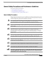
Warning

A readily accessible two-poled disconnect device must be incorporated in the fixed wiring.

Warning

You are in a situation that could cause bodily injury. Before you work on any equipment, be aware of
the hazards involved with electrical circuitry and be familiar with standard practices for preventing
accidents.

Warning

Never install telephone wiring during an electrical storm.

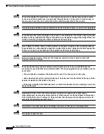
Warning

Do not reach into a vacant slot or chassis while you install or remove a card, a module, or a fan.
Exposed circuitry could constitute an energy hazard.

Warning

Blank faceplates and cover panels serve three important functions: they prevent exposure to
hazardous voltages and currents inside the chassis; they contain electromagnetic interference (EMI)
that might disrupt other equipment; and they direct the flow of cooling air through the chassis. Do not
operate the system unless all cards, faceplates, front covers, and rear covers are in place.

Warning

Never defeat the ground conductor or operate the equipment in the absence of a suitably installed
ground conductor. Contact the appropriate electrical inspection authority or an electrician if you are
uncertain that suitable grounding is available.

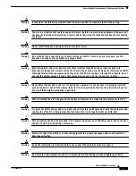
Warning

When installing the unit, the ground connection must always be made first and disconnected last.

Warning

For personal safety, the ground wire must connect to safety (earth) ground at both the equipment and
supply side of the DC wiring (unless the local electrical code requirements are different).

Warning

This equipment needs to be grounded. Use a green and yellow 12 to 14 AWG ground wire to connect
the host to earth ground during normal use.

Warning

Incorrect connection of this or connected equipment to a general purpose outlet could result in a
hazardous situation.

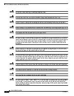
Warning

Read the installation instructions before you connect the system to its power source.

Warning

Do not work on the system or connect or disconnect cables during periods of lightning activity.

Summary of Contents for 6015

Page 1: ...riber line DSL interface module The DSL interface module is a field replaceable unit FRU Warning Only trained and qualified personnel should be allowed to install replace or service this equipment Contents This document includes the following sections Introduction page 2 Part and Tool Requirements page 4 General Safety Precautions and Maintenance Guidelines page 5 Removing and Installing the DSL I...

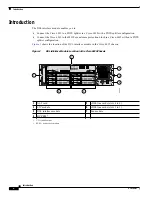
Page 2: ...ds slots 1 to 3 3 DSL interface module 7 Fan module 4 DC PEM2 2 PEM power entry module LNK S T A T T X T E S T R C L K S T A T R X CRITICAL MAJOR MINOR POWER STATUS ACTIVE FAN 1 FAN 2 ALARMS C N S L A U X E N E T ACO RESET ACT DS3 1 T1 E1 2 T1 E1 3 T1 E1 4 T1 E1 5 T1 E1 6 T1 E1 7 T1 E1 8 T1 E1 9 NI 2 DS3 T1 E1 IMA CAP ACTIVE STATUS 4X FLEXI DMT G LITE A1 A2 A3 A4 CAP ACTIVE STATUS 4X FLEXI DMT G L...

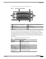
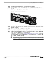
Page 3: ...efer to the Cisco 6015 Hardware Installation Guide for port mapping tables Table 1 lists the specifications for the DSL interface module 1 50 pin Champ connector for DSL slots 1 through 3 4 50 pin Champ connector for DSL slots 4 through 6 2 Cable tie downs 5 Extraction handle 3 Screws to secure the DSL interface module to the chassis 42373 DSL SLOTS 4 6 DSL SLOTS 1 3 2 1 5 2 3 4 3 Table 1 DSL Inte...

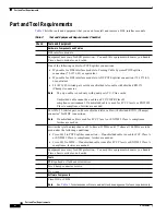
Page 4: ...d cable cannot be used in an FCC CISPR Class B compliance environment If unshielded cable is used for FCC Class A or EN55022 Class A compliance ferrites are needed 24 AWG 25 twisted pair solid core shielded telco cable with shielded RJ21X Champs connector2 for MDF connections Note If unshielded cable is used for FCC Class A or EN55022 Class A compliance ferrites are needed Ferrites that yield an i...

Page 5: ...formation and safety warnings Caution Proper ESD protection is required whenever you handle Cisco equipment Installation and maintenance personnel should be properly grounded by means of grounding straps to eliminate the risk of ESD damage to the equipment Equipment is subject to ESD damage whenever it is removed from the chassis Caution If fuses are already installed in the fuse and alarm panel r...

Page 6: ...n severe damage to the equipment and serious bodily injury Warning Before opening the chassis disconnect the telephone network cables to avoid contact with telephone network voltages Warning To prevent bodily injury when mounting or servicing this unit in a rack you must take special precautions to ensure that the system remains stable The following guidelines are provided to ensure your safety Th...

Page 7: ...ssis Do not operate the system unless all cards faceplates front covers and rear covers are in place Warning Never defeat the ground conductor or operate the equipment in the absence of a suitably installed ground conductor Contact the appropriate electrical inspection authority or an electrician if you are uncertain that suitable grounding is available Warning When installing the unit the ground ...

Page 8: ...e metal object to the equipment Warning Before working on a chassis or working near power supplies unplug the power cord on AC units disconnect the power at the circuit breaker on DC units Warning Do not touch the power supply when the power cord is connected For systems with a power switch line voltages are present within the power supply even when the power switch is off and the power cord is co...

Page 9: ...l storm There may be a remote risk of electric shock from lightning Warning Hazardous network voltages are present in WAN ports regardless of whether power to the router is OFF or ON To avoid electric shock use caution when working near WAN ports When detaching cables detach the end away from the router first Warning To reduce the risk of electric shock when servicing any individual unit disconnec...

Page 10: ... aligned properly with the module Ensure that the module is straight and not at an angle when you install the module in the slot Installing the module at an angle can damage the module Use the guide rails to install the module correctly Hot Swapping Modules The DSL interface module is a FRU however it is not hot swappable Removing the DSL interface module will interrupt the service for the entire ...

Page 11: ...or midplane Handle the modules by the extraction handles only avoid touching the printed circuit boards or connectors Place a removed component board side up on an antistatic surface or in a static shielding container If you plan to return the component to the factory immediately place it in a static shielding container Avoid contact between the printed circuit boards and clothing The wrist strap ...

Page 12: ... Step 4 Use a flat head or Phillips head screwdriver to unscrew the four screws that hold the DSL interface module to the Cisco 6015 chassis Step 5 Hold the extraction handle on the front of the module and firmly pull the module out of the slot See the Installing the DSL Interface Module section on page 12 for DSL interface module installation procedures Installing the DSL Interface Module Note If...

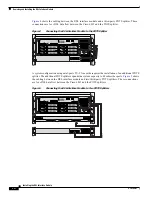
Page 13: ...without a POTS splitter configuration Use the cables that are described in the Part and Tool Requirements section on page 4 to connect the DSL interface module to the POTS splitter or MDF For cabling procedures for each POTS splitter refer to the appropriate vendor documentation Note If unshielded cable is used for FCC Class A or EN55022 Class A compliance the cables will need to be looped through...

Page 14: ...T1 E1 5 T1 E1 6 T1 E1 7 T1 E1 8 T1 E1 9 NI 2 DS3 T1 E1 IMA CAP ACTIVE STATUS 4X FLEXI DMT G LITE A1 A2 A3 A4 CAP ACTIVE STATUS 4X FLEXI DMT G LITE A1 A2 A3 A4 CAP ACTIVE STATUS 4X FLEXI DMT G LITE A1 A2 A3 A4 CAP ACTIVE STATUS 4X FLEXI DMT G LITE A1 A2 A3 A4 CAP ACTIVE STATUS 4X FLEXI DMT G LITE A1 A2 A3 A4 CAP ACTIVE STATUS 4X FLEXI DMT G LITE A1 A2 A3 A4 1 2 3 4 6 5 FAN 1 FAN 2 1 2 3 4 5 6 DS3 T...

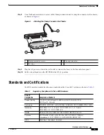
Page 15: ...face module has the same standards as the Cisco 6015 system as shown in Table 3 1 Champ connector screw 3 Champ connector 2 Tie wrap 48039 2 3 1 Table 3 Regulatory Compliance for Cisco 6015 Hardware Area of Compliance Compliance Standard Product Safety UL 1950 3rd Edition EN 60950 AS NZS 3260 IEC 950 FCC Part 15 Class B Emissions CISPR22 EN55022 AS ANS 3548 ICES 003 VCCI BSMI CNS 13438 Immunity EN...

Page 16: ...ipped with your product The Documentation CD ROM is updated monthly and may be more current than printed documentation The CD ROM package is available as a single unit or through an annual subscription Registered Cisco com users can order the Documentation CD ROM through the online Subscription Store http www cisco com go subscription Documentation Feedback If you are reading Cisco product documen...

Page 17: ...assessment training and certification programs You can self register on Cisco com to obtain customized information and service To access Cisco com go to the following URL http www cisco com Technical Assistance Center The Cisco TAC is available to all customers who need technical assistance with a Cisco product technology or solution Two types of support are available through the Cisco TAC the Cis...

Page 18: ... calling please check with your network operations center to determine the level of Cisco support services to which your company is entitled for example SMARTnet SMARTnet Onsite or Network Supported Accounts NSA In addition please have available your service agreement number and your product serial number This document is to be used in conjunction with the documents listed in the Related Documenta...

Reviews: