4-11
Cisco ASA 5580 Series Adaptive Security Appliance Hardware Installation Guide
OL-12920-01
Chapter 4 Maintenance and Upgrade Procedures
Removing and Installing Fans
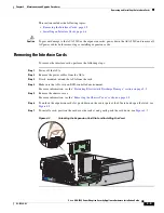
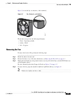
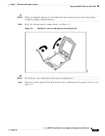
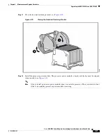
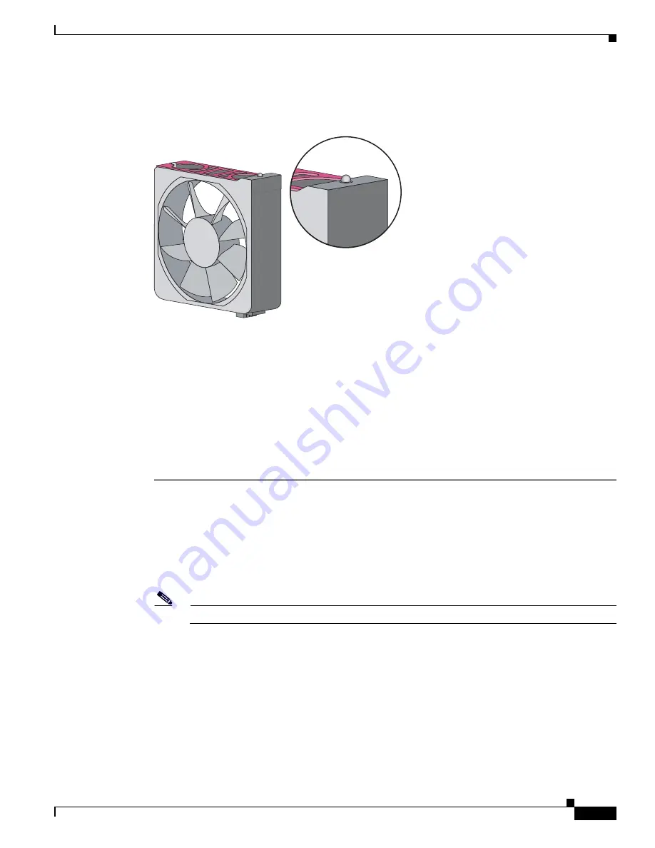
Figure 4-8
shows the fan, its connector, and its indicator.
Figure 4-8
Fan, Connector, and Indicator
The fan indicators provide the following information:
•
Green—Operating normally
•
Amber—Failed
•
Off— No power
Removing the Fan
To remove fans in the ASA, perform the following steps:
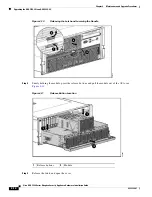
Step 1
Extend the chassis from the rack..
Step 2
Remove the chassis cover. For more information, see
Removing the Chassis Cover, page 4-2
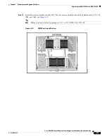
Step 3
Identify the failed fan by locating an amber indicator on top of the failed fan or a lighted FAN X indicator
on the Diagnostic Panel.
For more information about the Diagnostic Panel, see
Figure 1-5 on page 1-9
.
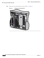
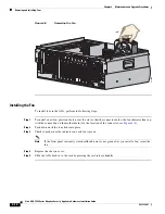
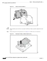
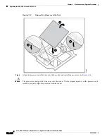
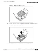
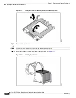
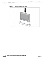
Step 4
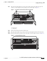
To remove the fan, grasp the red plastic handle and pull the handle up, see
Figure 4-9
.
Note
Remove and replace one fan at a time.
250251


