background image

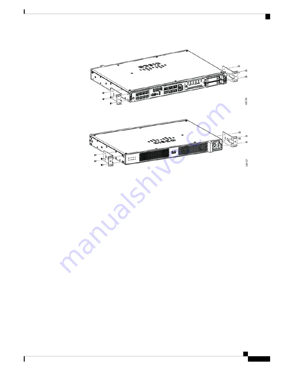
Figure 2: Bracket Installation for Front Mounting

Figure 3: Bracket Installation for Back Mounting

Mounting the device in a Rack

After you attach the brackets to the device, install the chassis on the rack as shown in Figure 8. You will need
two screws to attach each bracket to the rack; so, you will need four screws in total to attach the device to the
rack. The screws for attaching the device to the rack are not provided with the kit.

Installing the Device

3

Installing the Device

Rack-Mounting the Chassis

Summary of Contents for 5400 Series

Page 1: ...may be shipped in more than one container When you unpack the containers check the packing list to ensure that you have received all the items on the list Only unpack the product when you are ready to install it This will help prevent accidental damage LocatingtheProductID SerialNumber VersionIDandCommon Language Equipment Identifies CLEI The serial number SN product ID PID version ID VID and Comm...

Page 2: ...mount the device in the following ways Front mounting Brackets attached at the front of the chassis with the front panel facing forward Back mounting Brackets attached at the back of the chassis with the back panel facing forward Center front mounting Brackets attached in the center front of the chassis with the front panel facing forward Center back mounting Brackets attached in the center back o...

Page 3: ...ckets to the device install the chassis on the rack as shown in Figure 8 You will need two screws to attach each bracket to the rack so you will need four screws in total to attach the device to the rack The screws for attaching the device to the rack are not provided with the kit Installing the Device 3 Installing the Device Rack Mounting the Chassis ...

Page 4: ...mount the chassis 1 Attach the brackets to the device using the screws and plastic spacers provided with the mounting kit As shown in Figure 9 two screws and two plastic spaces should be used to attach each bracket to the chassis 2 Fix the router to the wall using the brackets that you attached to the device The screws for attaching the device to the wall are not provided with the kit Depending on...

Page 5: ... CIMC continues to be operational You must press this button again to power on the server Note 1 Attach the power cord to the power supply unit in the server and then attach the other end of the power chord to the grounded power outlet 2 Wait for approximately three minutes 3 Verify the power status of the system by looking at the system power status LED The power status LED blinks in amber color ...

Page 6: ...f the CIMC 4 After you have performed the required configuration save the setup and continue to boot Remote Connection Procedure 1 Plug in your terminal server to the Serial CIMC port Refer to Front panel of Chassis 2 Telnet into the console and perform the necessary configuration using corresponding commands You can also configure the IP address for the Ethernet CIMC port Use CIMC to configure th...

Reviews: