background image

16


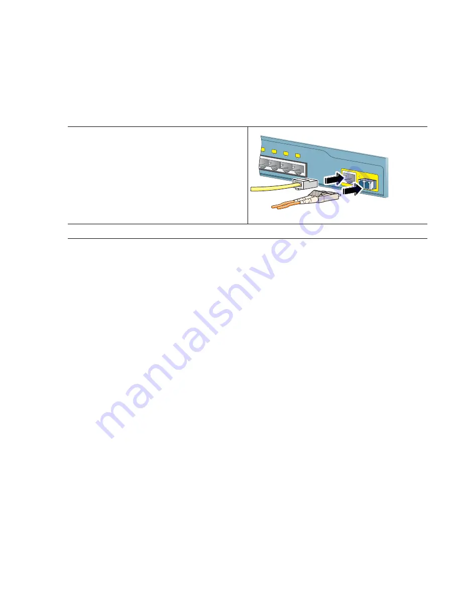
Connect to the Dual-Purpose Ports

Follow these steps:

Verify Port Connectivity

After you connect to the switch port and another device, the port LED turns amber while the switch 
establishes a link. This process takes about 30 seconds, and then the LED turns green when the switch 
and the target device have an established link. If the LED is off, the target device might not be turned 
on, there might be a cable problem, or there might be a problem with the adapter installed in the target 
device. See the “In Case of Difficulty” section on page 16 for information about online assistance.

7  

In Case of Difficulty

If you experience difficulty, help is available here and on Cisco.com. This section includes Express 
Setup troubleshooting, how to reset the switch, how to access help online, and where to find more 
information.

Step 1

Insert either an RJ-45 connector to the 
10/100/1000 port, or install an SFP module 
into the SFP module slot, and connect a cable 
to the SFP module port.

Only one port can be active at a time. If both 
ports are connected, the SFP module port has 
priority. The priority setting is not 
configurable.

Step 2

Insert the other cable end into the other device.

210090

5x

6x

7x

8x

1

Catalyst 2960


S

eries

Summary of Contents for 2960 8TC - Catalyst Switch

Page 1: ...LICENSE AND WARRANTY 1 About This Guide 2 Taking Out What You Need 3 Running Express Setup 4 Managing the Switch 5 Installing the Switch 6 Connecting to the Switch Ports 7 In Case of Difficulty 8 Obtaining Documentation and Submitting a Service Request 9 Cisco Limited Lifetime Hardware Terms ...

Page 2: ...cations refer to the documents that match the Cisco IOS software version running on the switch You can use the show version command to display software version information For translations of the warnings that appear in this publication see the Regulatory Compliance and Safety Information for the Catalyst 2960 Switch that accompanies this guide 2 Taking Out What You Need Follow these steps 1 Unpac...

Page 3: ... AC powered switches only 4 Three number 8 Phillips pan head screws 8 Console cable R e g u l a t o r y C o m p l i a n c e a n d S a f e t y I n f o r m a t i o n f o r t h e C a t a l y s t 2 9 6 0 S w i t c h D o c u m e n t a t i o n C D 1 2 3 4 5 6 7 8 202600 Catalyst 2960 Series CONSOLE 1x SPD DPLX STAT SYST MODE 2x 3x 4x 5x 6x 7x 8x 1 ...

Page 4: ...itch Step 3 When the switch powers on it begins the power on self test POST During POST the LEDs blink while tests verify that the switch functions properly Wait for the switch to complete POST which can take several minutes Step 4 Verify that POST has completed by confirming that the SYST LED remains green If the switch fails POST the SYST LED turns amber POST errors are usually fatal Contact you...

Page 5: ...e LEDs on both Ethernet ports are green Wait 30 seconds Step 9 Start a web browser on your PC Enter the IP address 10 0 0 1 in the web browser and press Enter The Express Setup page appears If it does not appear see the In Case of Difficulty section on page 16 for help Your entries should be in English DHCP enabled PC 210109 2x 3x 4x 5x 6x 7x 8x 1 Catalyst 2960Series CONSOLE 1x SPD DPLX STAT SYST ...

Page 6: ...llowed In the System Contact field enter the name of the person responsible for the switch In the System Location field enter the wiring closet floor or building where the switch is located In the Telnet Access field click Enable if you are going to use Telnet to manage the switch by using the command line interface CLI If you enable Telnet access you must enter a Telnet password In the Telnet Pas...

Page 7: ...low these steps 1 Start a web browser on your PC or workstation 2 Enter the switch IP address in the web browser and press Enter The device manager page appears 3 Use the device manager to perform basic switch configuration and monitoring Refer to the device manager online help for more information 4 For a more advanced configuration install Cisco Network Assistant as described in the next section...

Page 8: ...twork Assistant online help and the getting started guide for more information Command Line Interface You can enter Cisco IOS commands and parameters through the CLI Access the CLI either by connecting your PC directly to the switch console port or through a Telnet session from a remote PC or workstation Follow these steps 1 Connect the supplied RJ 45 to DB 9 adapter cable to the 9 pin serial port...

Page 9: ...lyst 2960PD 8TT L switches For information applicable to the other Catalyst 2960 switches see the Catalyst 2960 Switch Hardware Installation Guide on Cisco com which includes installation instructions for all Catalyst 2960 switch models This section covers desk shelf and magnet mounting As an example all the illustrations show the Catalyst 2960 8TC switch For alternate mounting procedures such as ...

Page 10: ...ut the magnet we strongly recommend that you attach the rubber feet to the switch Doing so helps prevent airflow restriction and overheating Do not stack switches or place switches side by side unless they are separated all around by at least 3 inches 7 6 cm of clearance from each other Do not wall mount the switch with its front panel facing up or to the side We recommend wall mounting the switch...

Page 11: ...ection describes installation information specific to the Catalyst 2960 8TC and Catalyst 2960G 8TC switches For information applicable to the other Catalyst 2960 switches see the Catalyst 2960 Switch Hardware Installation Guide on Cisco com To place the switch on a desk without using the mounting screws simply attach the four rubber feet on the bottom panel of the switch To secure the switch on to...

Page 12: ...Screws 4 Place the switch onto the mounting screws and slide it forward until it locks in place see Figure 2 Figure 2 Placing the Switch on the Mounting Screws 1 3 2 210096 2x 3x 4x 5x 6x 7x 8x 1 Catalyst 2960Series CONSOLE 1x SPD DPLX STAT SYST MODE 210094 ...

Page 13: ...he mounting magnet on the mounting surface see Figure 3 2 Place the bottom of the switch on the mounting magnet see Figure 3 Figure 3 Mounting the Switch with a Magnet Panel 1 Ca ta ly st 29 60 S erie s STA T DPL X SPD SYS T 1x 2x 3x 4x 5x 6x 7x 8x CO NS OL E 2 1 3 210097 ...

Page 14: ...Ethernet connections and configures the interfaces accordingly Therefore you can use either a crossover or a straight through cable for connections to a switch 10 100 or 10 100 1000 Ethernet port regardless of the type of device on the other end of the connection Step 1 When you connect to servers workstations IP phones wireless access points and routers insert a straight through twisted four pair...

Page 15: ...emoving and installing an SFP module can shorten its useful life Do not remove and insert SFP modules more often than is absolutely necessary Step 1 Grasp the module on the sides and insert it into the switch slot until you feel the connector snap into place Step 2 Insert an appropriate cable into the module port Step 3 Insert the other cable end into the other device SFP module 210088 5x 6x 7x 8x...

Page 16: ...n Case of Difficulty section on page 16 for information about online assistance 7 In Case of Difficulty If you experience difficulty help is available here and on Cisco com This section includes Express Setup troubleshooting how to reset the switch how to access help online and where to find more information Step 1 Insert either an RJ 45 connector to the 10 100 1000 port or install an SFP module i...

Page 17: ...your PC have a static IP address If yes change your PC settings to temporarily use DHCP before connecting to the switch Did you connect a crossover cable instead of a straight through Ethernet cable between a switch port and the Ethernet port of the PC If yes connect a straight through cable to an Ethernet port on the switch and the PC Wait 30 seconds before entering 10 0 0 1 in the browser Did yo...

Page 18: ... switch reboots The switch now behaves like an unconfigured switch You can enter the switch IP information by using Express Setup as described in the Running Express Setup section on page 4 Accessing Help Online First look for a solution to your problem in the troubleshooting section of the Catalyst 2960 Switch Hardware Installation Guide or the Catalyst 2960 Switch Software Configuration Guide on...

Page 19: ...reference provides detailed descriptions of the Cisco IOS commands specifically created or modified for the switch Catalyst 3750 3560 3550 2970 and 2960 Switch System Message Guide This guide provides descriptions of the system messages specifically created or modified for the switch Device manager online help available on the switch Cisco Network Assistant online help available on the switch 8 Ob...

Page 20: ... b Select the language in which you would like to read the document c Click Go The Cisco Limited Warranty and Software License page from the Information Packet appears d Read the document online or click the PDF icon to download and print the document in Adobe Portable Document Format PDF Note You must have Adobe Acrobat Reader to view and print PDF files You can download the reader from Adobe s w...

Page 21: ...easonable efforts to ship a replacement part within ten 10 working days after receipt of the Return Materials Authorization RMA request Actual delivery times can vary depending on the customer location Cisco reserves the right to refund the purchase price as its exclusive warranty remedy To Receive a Return Materials Authorization RMA Number Contact the company from whom you purchased the product ...

Page 22: ... Access Registrar Aironet Catalyst CCDA CCDP CCIE CCIP CCNA CCNP CCSP Cisco the Cisco Certified Internetwork Expert logo Cisco IOS Cisco Press Cisco Systems Cisco Systems Capital the Cisco Systems logo Cisco Unity Enterprise Solver EtherChannel EtherFast EtherSwitch Fast Step Follow Me Browsing FormShare GigaDrive HomeLink Internet Quotient IOS iPhone IP TV iQ Expertise the iQ logo iQ Net Readines...

Reviews: