


VCC-5CL4MHS
Rev.905-0079-01
©2017 CIS Corporation. All rights reserved.
5
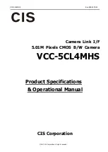
100
Ω
FVAL Output
LVAL Output
DVAL Output
Exposure Output
+5.0V(VCC)
Trigger Input
HD74LV1GT32ACME(RENESAS)
Voh:3.8V(Min)
Vol:0.55V(Max)
1K
Ω
HD74LV1GT14ACME(RENESAS)
Vt-:0.5(Min)
Vt+:1.9V(Max)
100
Ω
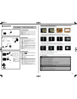
4.2.
Camera Input and Output Signals Specifications
(1)Video Output Data Effective Video Output
2448(H) × 2048(V)
At full frame scan mode
(2) Sync. Signal
output
LVAL
:No. 6 pin
12pins circular connector
(LVTTL output)
FVAL
:No. 7 pin
EXPOSURE
:No. 9 pin
DVAL
:No.10pin
LVAL
FVAL
Camera Link output (LVDS)
(3)Trigger input
Polarity
Positive/Negative
selectable
Pulse width
1H(min)
~
Approx. 2 frames
Functionally, no upper limitation is set but at long time
exposure, dark noises and shading noises might be noticeable.
Trigger input
:No.11 pin 12pins circular connector (LVTTL)
:CC1
Camera Link input (LVDS)
(5)Serial
communications
SerTC
(Serial to Camera)
Camera Link input (LVDS
)
SerTFG (Serial to Frame Grabber)
Camera Link output (LVDS)
Video signals
White Clip Level
At Digital 8bit
: FFh
Setup Level
At Digital 8bit
: 2
±
1h
(Condition: Gain 0dB)
Dark Shading
At Digital 8bit
: Both horizontal and vertical should be
under 04h. (Condition: Gain 0dB)
IO Interface of 12pins Circular connector at rear