background image

CIS

-

CRS354

-

48P MANAGED L3 NETWORK SWITCH


PRODUCT MANUAL


1. Welcome to Custom Integration Solutions


Thank you for purchasing CIS devices. Our solutions make it easy for integrators to deploy networks in home and business 
settings with minimal configuration. Our support team can provide assistance in setting up the equipment and answering your 
questions.


3. Overview


The CIS

-

CRS354

-

48P is a high performance managed switch that provides PoE on each of its 48 Gigabit Ethernet ports.


In addition to the PoE Ethernet ports, there are 4 SFP+ ports (up to 10 Gbps), and 2 QSFP+ ports (up to 40 Gbps).


The device is pre

-

configured with all ports switched together. We recommend you to set up a password to secure your device. 


This unit is compatible with 1.25G SFP and 10G SFP+ modules. The device is capable of powering other devices through PoE.


Power


The unit is equipped with one IEC type AC power input, which accepts 100

-

240 V power (~ 50/60 Hz).


The power consumption of this device under maximum load is 800 W with attachments, 85 W without attachments.


PoE output


This device can supply PoE to external devices. The output voltage will be selected automatically, depending on the voltage 

the connected device requires. The device can power both 802.3af/at devices and devices that accept passive PoE power. If 

necessary, the output voltage can be switched manually. 


By default the PoE mode is set to auto. It will not damage non

-

PoE devices and will auto

-

detect devices with PoE support and 

their required voltage. Once a PoE device is detected, it will be powered and the PoE LEDs will turn on.


The switch can output a total of 1000 mA per port at <30 V, and 570 mA at >30 V. The total current output at 26 V is 27A, and 

13.2 A at 53V.


The max wattage per port is 26 W at 26 V, and 30 W at 53 V.
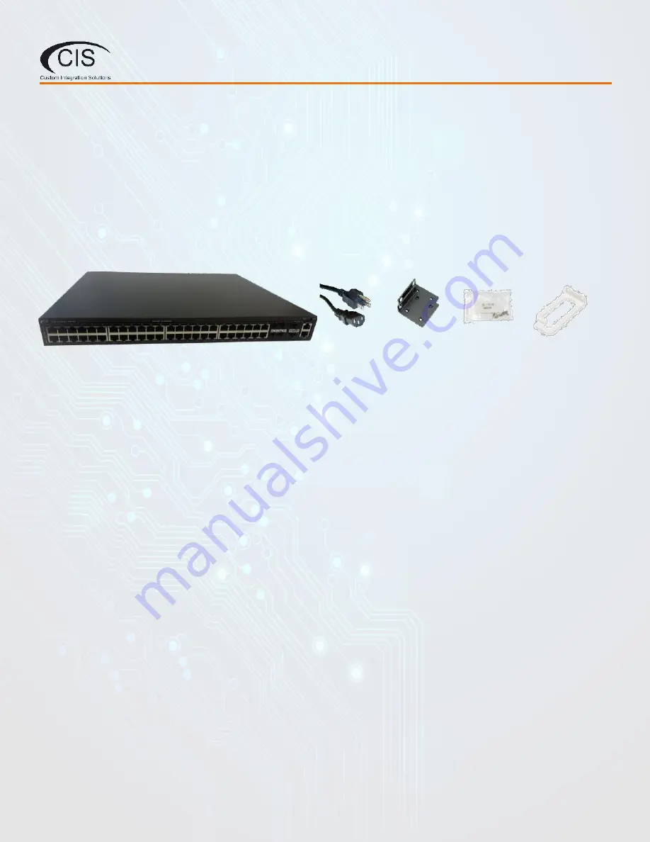
 

2. Package Contents


Switch (1)

Rack Ears (2)


Rack hooks (2)


Rear supports (2)


IEC Power 

Cord (1)


Rack 


Screws 


Cable Management 

Brackets (2)


Summary of Contents for CIS-CRS354-48P

Page 1: ...CIS CRS354 48P MANAGED L3 NETWORK SWITCH PRODUCT MANUAL...

Page 2: ...LED Indicators 5 Buttons 5 Input Power Requirements 5 4 Rackmount Instructions 6 5 Accessing the Web Interface 7 The Status Page 7 Set the System Identity 8 The Undo and Redo Buttons 8 Show Hide Passw...

Page 3: ...12 Loop Protect 13 8 VLANs 14 Purchase VLAN Configuration 14 VLAN Configuration 14 Adding Ports to the VLAN s 15 9 PoE Information and Settings 16 PoE Out Modes 16 PoE Out Limitations 16 Enable Disabl...

Page 4: ...equipped with one IEC type AC power input which accepts 100 240 V power 50 60 Hz The power consumption of this device under maximum load is 800 W with attachments 85 W without attachments PoE output...

Page 5: ...t has occurred Contact CIS if this light is lit The top row LEDs indicate PoE out status A green LED indicates that the respective port uses low voltage a red LED indicates high voltage The direction...

Page 6: ...ve the switch into place using the rear supports to hold it Attach the switch to the front of the rack with rack screws 5 Attach the cable management brackets to the rack optional 1 Attach the rack ea...

Page 7: ...pen a web browser and enter the IP address in the address bar 3 To login enter the username cis and password integration 4 Integrators may use the Get TeamViewer link if remote assistance is required...

Page 8: ...at can uniquely identify it The Identity setting can be found in the System tab in the left toolbar Undo Redo Undo and Redo buttons are located in the left toolbar You may use them to quickly undo red...

Page 9: ...security of the device Rebooting the Device CIS discourages rebooting your switches If you are having ongoing issues with your network and suspect a reboot will help the Reboot option can be found un...

Page 10: ...equire a different network address please contact CIS Services for assistance The DHCP Client tab The DHCP Client tab will present you with the IP address assigned to the switch from your router This...

Page 11: ...ting a static address perform an IP scan on the LAN to confirm available addresses see the tools section In the address field set the address you would like to use for the switch Ping the switch to co...

Page 12: ...on all ports You can view the traffic sent and received the status of PoE PoE settings PoE priority and current being drawn by PoE devices Power Cycling To power cycle a port select the Power Cycle b...

Page 13: ...e works by checking the source MAC address of received loop protect packet against MAC addresses of loop protect enabled interfaces If the match is found loop protect dis ables the interface that rece...

Page 14: ...CIS Store Additional components are required for VLANs to function https www custom integration solutions com store cis vlan interface https www custom integration solutions com store cis additional...

Page 15: ...en created a bridge interface will be selectable on the Bridge Ports tab Select the ethernet port to link to your VLAN Select the bridge from the drop down menu This port will now access the IP addres...

Page 16: ...s if an overload or a short circuit is detected After the cable is unplugged the power still remains enabled on the port Off mode If off mode is used PoE Out on the port will be turned off no detectio...

Page 17: ...lbar UPnP CIS devices support Universal Plug and Play architecture for transparent peer to peer network connectivity of network enabled intelligent devices or appliances UPnP allows a wide range of de...

Page 18: ...he tool will attempt to scan all addresses or addresses in a specific range For example 10 100 1 0 24 Device interfaces The tool will listen to packets that are passing by and attempt to compile resul...

Page 19: ...to products that have been abused modified or disassembled Products to be repaired under this warranty must be returned to Custom Integration Solutions or a designated service center with prior notifi...

Reviews: