CDB4923 CDB49300
DS262DB2
47
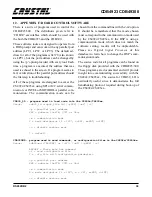
16. APPENDIX J: SWITCH SUMMARY
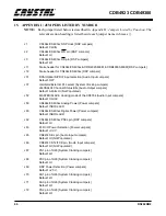
Table 18 lists the jumper settings required for all
four host interface modes of the CS492x/CS493xx.
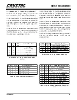
Table 19 shows all of the digital output formats that
can be selected for the CS5334 with switch S4.
Please see the CS5334 datasheet for a more de-
tailed description of available digital output for-
mats.
Table 20 shows all of the digital input formats that
can be selected for the CS4340 with S4. Please see
the CS4340 datasheet for a more detailed descrip-
tion of available digital input formats.
Table 21 shows all of the digital output formats that
can be selected for the CS8414 with switch S1.
Please see the CS8414 datasheet for a more de-
tailed description of available audio serial port for-
mats.
Table 23 shows all of the digital input formats that
can be selected for the CS8404A with switch S2.
Please see the CS8404A datasheet for a more de-
tailed description of available digital input format.
Table 22. shows all available PLL settings for the
external PLL on the CDB4923/4930.
Table 24 lists all possible data routing possibilities
and the associated MCLK source for the
CDB4923/300.
RD
J3
WR
J2
PSEL
J62
Host Interface Mode
0
1
1
Serial I
2
C
(PSEL == SCDIO)
1
0
X
Serial SPI
1
1
0
8-bit Intel
1
1
1
8-bit Motorola
Table 18. CS492x/CS493xx Host Interface Mode
Selection
34DIF1
34DIF0
Digital Input Format
LO
LO
20-Bit Left Justified, Rising SCLK
LO
HI
20-Bit Left Justified, Falling SCLK
HI
LO
20 Bit I
2
S, Rising SCLK (default)
HI
HI
Power Down
Table 19. CS5334 Digital Output Formats (S4)
27DIF1
27DIF0
Digital Input Format
LO
LO
16-24 Bit I
2
S (default)
LO
HI
16-24 Bit Left Justified
HI
LO
24-Bit Right Justified
HI
HI
16-Bit Right Justified
Table 20. CS4340 Digital Input Formats (S4)
M2
M1
M0
Audio Serial Port Format
LO
LO
LO
Out, L/R, 16-24 Bits
LO
LO
HI
In, L/R, 16-24 Bits
LO
HI
LO
Out, L/R, I
2
S Compatible
LO
HI
HI
In, L/R, I
2
S (default)
HI
LO
LO
Out, WSYNC, 16-24 Bits
HI
LO
HI
Out, L/R, 16 Bits LSBJ
HI
HI
LO
Out, L/R, 18 Bits LSBJ
HI
HI
HI
Out, L/R, MSB Last
Table 21. Digital Output Format settings for CS8414
(S1)
Summary of Contents for CS492 Series
Page 18: ...CDB4923 CDB49300 18 DS262DB2 9 APPENDIX A SCHEMATICS Figure 4 CS492x CS493xx ...
Page 19: ...CDB4923 CDB49300 DS262DB2 19 Figure 5 System Power ...
Page 20: ...CDB4923 CDB49300 20 DS262DB2 Figure 6 PC Interface ...
Page 21: ...CDB4923 CDB49300 DS262DB2 21 Figure 7 Control Logic ...
Page 22: ...CDB4923 CDB49300 22 DS262DB2 Figure 8 Clocking ...
Page 23: ...CDB4923 CDB49300 DS262DB2 23 Figure 9 Analog Input ...
Page 24: ...CDB4923 CDB49300 24 DS262DB2 Figure 10 Digital Input ...
Page 25: ...CDB4923 CDB49300 DS262DB2 25 Figure 11 D A Converters ...
Page 26: ...CDB4923 CDB49300 26 DS262DB2 Figure 12 Analog Output ...
Page 27: ...CDB4923 CDB49300 DS262DB2 27 Figure 13 Digital Output ...
Page 28: ...CDB4923 CDB49300 28 DS262DB2 Figure 14 Top Layer ...
Page 29: ...CDB4923 CDB49300 DS262DB2 29 Figure 15 Bottom Layer ...
Page 30: ...CDB4923 CDB49300 30 DS262DB2 Figure 16 SSTOP ...
Page 31: ...CDB4923 CDB49300 DS262DB2 31 Figure 17 ASYSTOP ...
Page 32: ...CDB4923 CDB49300 32 DS262DB2 Figure 18 Layer 2 ...
Page 33: ...CDB4923 CDB49300 DS262DB2 33 Figure 19 Layer 3 ...
Page 49: ... Notes ...
Page 50: ......

