


45
CS42426
5.15
ADC Left Channel Gain (address 1Ch)
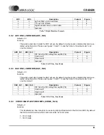
5.15.1 ADC LEFT CHANNEL GAIN (LGAINX)
Default = 00h
Function:
The level of the left analog channel can be adjusted in 1 dB increments as dictated by the Soft and
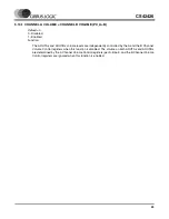
Zero Cross bits (SZC[1:0]) from +15 to -15 dB. Levels are decoded in two’s complement, as shown
in Table 16.
5.16
ADC Right Channel Gain (address 1Dh)
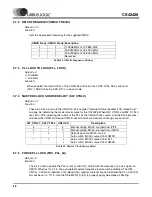
5.16.1 ADC RIGHT CHANNEL GAIN (RGAINX)
Default = 00h
Function:
The level of the right analog channel can be adjusted in 1dB increments as dictated by the Soft and
Zero Cross bits (SZC[1:0]) from +15 to -15dB. Levels are decoded in two’s complement, as shown in
Table 16.
5.17
Interrupt Control (address 1Eh)
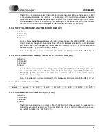
5.17.1 SERIAL PORT SYNCHRONIZATION (SP_SYNC)
Default = 0
0 - DAC & ADC Serial Port timings not in phase
1 - DAC & ADC Serial Port timings are in phase
Function:
Forces the LRCK and SCLK from the DAC & ADC Serial Ports to align and operate in phase. This
function will operate when both ports are running at the same sample rate or when operating at dif-
ferent sample rates.
7
6
5
4
3
2
1
0
Reserved
Reserved
LGAIN5
LGAIN4
LGAIN3
LGAIN2
LGAIN1
LGAIN0
7
6
5
4
3
2
1
0
Reserved
Reserved
RGAIN5
RGAIN4
RGAIN3
RGAIN2
RGAIN1
RGAIN0
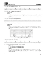
Binary Code
Decimal Value
Volume Setting
001111
+15
+15 dB
001010
+10
+10 dB
000101
+5
+5 dB
000000
0
0 dB
111011
-5
-5 dB
110110
-10
-10 dB
110001
-15
-15 dB
Table 16. Example ADC Input Gain Settings
7
6
5
4
3
2
1
0
SP_SYNC
Reserved
DE-EMPH1
DE-EMPH0
INT1
INT0
Reserved
Reserved


