DS241RD1C1
3
CRD4610-1
CrystalClear™ AC '97 Motherboard Reference Design
CIRRUS LOGIC ADVANCED PRODUCT DATABOOK
For information regarding the programming and
timing of the EEPROM, refer to the CS4610 Data
Sheet [3].
CS4297 Audio Codec ‘97 Section
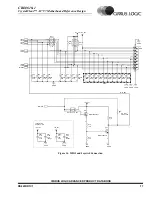
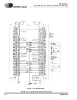
This section contains the components for the Mic
In, Line In, and Line Out audio connections. It also
includes a 24.576 MHz crystal that acts as the mas-
ter clock in an AC ‘97 configuration. The capaci-
tors required for the CS4297 and their placement
are discussed in the CS4297 Data Sheet. Refer to
the Grounding and Layout section of the data sheet
for the recommended routing the audio section [4].
The required area for this particular layout is 1.08
sq. in.
Optional Extended Analog I/O Section
The CS4297 has many analog inputs and outputs
that may or may not be used depending on the sys-
tem’s application. Unused inputs should be tied to
Vrefout (pin 28) or capacitively coupled to the an-
alog ground plane. The optional section contains
the components for a headphone amplifier and an-
other microphone amplifier for the MIC2 input.
This section also contains a population option for
headphones or headset operation on the 1/8" exter-
nal jack. The reference card ships with headphone
operation enabled. To enable headset operation,
R24 and R26 should be removed and one of the re-
sistors placed in the space for R25. This will enable
the microphone 2 input on the tip connection of the
external jack and the right headphone channel on
the ring connection of the external jack.
The Modem Audio, CD ROM, Video In, Aux in,
and Spk In headers are also part of the Extended
Analog I/O section. Each header has a few resistor
packs and capacitors associated with it. The header
and its associated components may or may not be
necessary depending on the audio inputs imple-
mented.
Audio Inputs and Outputs
The entire set of the CS4297’s analog I/O is repre-
sented on the reference design card through inter-
nal headers and external connectors:
-
Line Out
-
Mic In
-
Line In
-
CD ROM In
-
Modem audio connection
-
Headphone Out or Headset connection
-
Aux In
-
Video In
-
PC Speaker
Five external 1/8" jacks and six internal header
connections are used for analog inputs and outputs.
The modem audio connection and the line out con-
nection have an internal header and an external 1/8"
jack connection. When a plug is inserted into the
external jack for the modem audio or the line out
connections, the corresponding internal connector
is disabled.
The line out, line in and microphone in circuits are
included in the area outlined around the CS4297
codec. The other analog connections are consid-
ered to be part of the optional extended analog I/O.
Line Out
The Line Out connection can either be made
through the external 1/8" jack or the internal 4-pin
(0.1 inch center) header. If the 1/8" jack is used the
internal 4 pin connector is disabled. The Line Out
output can only drive input impedances greater
than 10 k
Ω
.
•
Maximum output level: 1 Vrms
Summary of Contents for CRD4610-1
Page 30: ......


