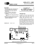
Cirrus Logic CRD4297-1 AMR Product Data Book Download Page 3

DS242RD1B1

3

CRD4297-1 AMR

CrystalClear™ AC '97 AMR Audio Modem Riser Reference 

CIRRUS LOGIC ADVANCED PRODUCT DATABOOK

alog mixer, a stereo ADC, a stereo DAC, and a con-
trol and digital audio stream interface to the AC ‘97
controller.

The CS4297 contains two distinct functional sec-
tions: digital and analog. The digital section in-
cludes the AC-link registers, power management
support, SYNC detection circuitry, and AC-link se-
rial port interface logic. The analog section in-
cludes the analog input multiplexer (mux), stereo
output mixer, mono output mixer, stereo ADCs,
stereo DACs, and analog volume controls. This
section contains the components for the various an-
alog audio connections, and the 24.576 MHz crys-
tal master clock. For more information refer to the
CS4297 Data Sheet [3]. The capacitors required for
the CS4297 and their placement are discussed in
the CS4297 Data Sheet [3]. Refer to the Grounding
and Layout
 section of the data sheet for the recom-
mended routing of the audio section.

Power Requirements

The CS4297 requires both a d3.3 V and an
5 V supply. The digital power is supplied
from the AMR bus. A voltage regulator is recom-
mended for the analog supply. A Motorola
MC78L05 regulates the AMR +12 V supply down
to provide a clean +5 V analog supply for the
CS4297. The MC78L05 regulator can provide ade-
quate current, which is enough for the CS4297 and
associated analog circuitry. 

Analog I/O 

The CS4297 has many analog inputs and outputs
that may or may not be used depending on the sys-
tem’s application. Unused inputs should be tied to
Vrefout (pin 28) or capacitively coupled via 0.1 µF
to the analog ground plane. The analog section con-
tains the components for a headphone amplifier.
The Modem Audio, CD In, Audio In, and Aux In
headers are also part of the Analog I/O section. The

header and its associated components may or may
not be necessary depending on the audio inputs im-
plemented.

Audio I/O

A full feature set of the CS4297’s analog I/O and
digital out is represented on the reference design
card through internal and external connectors:

Line  Out

Headphone Out

Line  In

Mic  In

CD Audio In

Aux In

Video  In

Modem Audio connection

Optical Digital Out

Four external 1/8" jacks, one external TOS-LINK
jack, and four internal header connections are used
for analog and digital inputs and outputs.

Line Out

The output of the CS4297 is capable of driving im-
pedances greater than 10 k

Ω 

with a maximum out-

put voltage of 1 Vrms. The Line Out connection is
made via an external 1/8" jack. 

Maximum output level: 1 Vrms

Headphone Out

An external 1/8" jack provided for a headphone
connection. This output is driven by an amplifier
for low impedance loads such as 32 

 headphones.

Maximum output level: 2.0 Vrms (no load);
1.5 Vrms (32

 load)

Maximum output power: 70 mW/channel
(32

 load)

Summary of Contents for CRD4297-1 AMR

Page 1: ...mance requirements DESCRIPTION The CRD4297 1 AMR add in board reference design showcases Cirrus Logic s Crystal Audio AC 97 CS4297 SoundFusion Audio Codec 97 and is Au dio Modem Riser Specification 2 compliant The CRD4297 1 AMR card is 2 7 high by 3 6 long The CRD4297 1 AMR reference design includes a cus tomer ready manufacturing kit Included in the kit are a full set of schematic design files Or...

Page 2: ...allic insulator thereby preventing ground loops and electromagnetic interference For signal transmission it offers low attenuation high bandwidth low propagation delay low bit er ror rates small size and cost efficiency The signal is IEC 958 and CP 1201 compliant CS4297 Audio Codec 97 The CS4297 is a mixed signal serial Codec based on the AC 97 specification It is designed to be paired with a digi...

Page 3: ...5 regulator can provide ade quate current which is enough for the CS4297 and associated analog circuitry Analog I O The CS4297 has many analog inputs and outputs that may or may not be used depending on the sys tem s application Unused inputs should be tied to Vrefout pin 28 or capacitively coupled via 0 1 µF to the analog ground plane The analog section con tains the components for a headphone am...

Page 4: ... connector Wired as Pin 1 Left Channel Pin 2 Analog Ground Pin 3 Analog Ground Pin 4 Right Channel Maximum input level 2 Vrms Video In Internal 4 pin 0 1 inch center right angled connector Pin 1 Left Channel Pin 2 Analog Ground Pin 3 Analog Ground Pin 4 Right Channel Maximum input level 2 Vrms Modem Audio Connection The modem audio connection can be made through the internal 4 pin 0 1 inch center ...

Page 5: ... is located near the CS4297 A 10 µF electrolytic capacitor should be added next to pins 25 and 26 if the capacitor con nected to the output of the power regulator is locat ed far away from the CS4297 All filtering capacitors of audio signals are NPO type to ensure minimal added distortion Two footprints are pro vided for the crystal XTAL a CA 301 pin in hole footprint Y1 for miniature crystal and ...

Page 6: ...kage are supported EMC Components A number of capacitors and inductors are included to help the board meet EMC compliance tests such as FCC Part 15 Modifying this selection of compo nents without EMC testing could cause EMC com pliance failure GROUNDING AND LAYOUT Partitioned Voltage and Ground Planes The pinout of the CS4297 allows the ground split to completely separate digital signals on one si...

Page 7: ...abeled at the top LEFT indi cating that the bottom set of data is the left channel and associated with the left vertical axis Signal Name Connector Maximum Voltage Reference Designator Imp kΩ Line In Jack 2 341 VRMS 0 dB FS li Mic In Jack 0 146 VRMS 0 dB FS mi Line Out Jack 1 058 VRMS 0 dB FS lo N A Speaker Out 8Ω N A N A 0 dB FS so N A Microphones Supported Support Comments 3 Pin Phantom Power po...

Page 8: ...0 1 2 3 4 97 1 97 1MXL ADX LEFT RIGHT Frequency Hz Amplitude dB Amplitude dB Figure 1 Full Duplex A D PC D A Line In Out Frequency Response CwGRAPH 0 65 CrystalWare tm 20 100 1 k 10 k 20 k 60 65 70 75 80 85 90 95 100 105 110 50 55 60 65 70 75 80 85 90 95 100 97 1 97 1NXL ADX LEFT RIGHT Frequency Hz Dynamic Range dB FS A Dynamic Range dB FS A Figure 2 Full Duplex A D PC D A Line In Out Dynamic Rang...

Page 9: ... 100 105 110 50 55 60 65 70 75 80 85 90 95 100 97 1 97 1DXL ADX LEFT RIGHT Frequency Hz THD N dB FS THD N dB FS Figure 3 Full Duplex A D PC D A Line In Out THD N vs Frequency CwGRAPH 0 65 CrystalWare tm 20 100 1 k 10 k 20 k 3 2 1 0 1 2 3 4 5 6 7 6 5 4 3 2 1 0 1 2 3 4 97 1 97 1MAL ADX LEFT RIGHT Frequency Hz Amplitude dB Amplitude dB Figure 4 Analog Mixer A A Line In Out Frequency Response ...

Page 10: ...55 60 65 70 75 80 85 90 95 100 97 1 97 1NAL ADX LEFT RIGHT Frequency Hz Dynamic Range dB FS A Dynamic Range dB FS A Figure 5 Analog Mixer A A Line In Out Dynamic Range CwGRAPH 0 65 CrystalWare tm 20 100 1 k 10 k 20 k 60 65 70 75 80 85 90 95 100 105 110 50 55 60 65 70 75 80 85 90 95 100 97 1 97 1DAL ADX LEFT RIGHT Frequency Hz THD N dB FS THD N dB FS Figure 6 Analog Mixer A A Line In Out THD N vs F...

Page 11: ... tm 20 100 1 k 10 k 20 k 3 2 1 0 1 2 3 4 5 6 7 97 1 97 1MAM ADX Frequency Hz Amplitude dB Figure 7 Analog Mixer A A Mic In Line Out Frequency Response CwGRAPH 0 65 CrystalWare tm 20 100 1 k 10 k 20 k 60 65 70 75 80 85 90 95 100 105 110 97 1 97 1NAM ADX Frequency Hz Dynamic Range dB FS A Figure 8 Analog Mixer A A Mic In Line Out Dynamic Range ...

Page 12: ...20 100 1 k 10 k 20 k 60 65 70 75 80 85 90 95 100 105 110 97 1 97 1DAM ADX Frequency Hz THD N dB FS Figure 9 Analog Mixer A A Mic In Line Out THD N vs Frequency CwGRAPH 0 65 CrystalWare tm 20 100 1 k 10 k 20 k 50 55 60 65 70 75 80 85 90 95 100 97 1 97 1CAL ADX Frequency Hz Crosstalk dB Figure 10 Analog Mixer A A Line In Out Crosstalk vs Frequency ...

Page 13: ...platform ac97 INDEX HTM 3 Cirrus Logic CS4297 SoundFusion Audio Codec 97 Data Sheet July 1998 http www cirrus com products overviews cs4297 html 4 Steve Harris Clif Sanchez Personal Computer Audio Quality Measurements Ver 0 5 http www cirrus com products papers meas meas html 5 Intel and Microsoft PC 99 System Design Guide http www microsoft com hwdev desguid 6 M Montrose Printed Circuit Board Des...

Page 14: ... D N A B I T C L K CD_COM LINE_IN_L MIC1 ALT_LINE_OUT_L AUX_INL AUX_INR VIDEO_L VIDEO_R M S T R C L K AMR_BUS AMR_BUS A R S T A B I T C L K A S Y N C A S D I N A S D O U T P R I M A RY _ D N M S T R C LK S PDIF_OUT S P D I F _ C O D E C PC_BEEP_BUS AUDIO_OUT AUDIO_OUT ALT_LINE_OUT_L ALT_LINE_OUT_R LINE_OUT_R LINE_OUT_L S P D I F _ O U T POWER POWER PC_BEEP CD_INL CD_COM CD_INR LINE_IN_L LINE_IN_R ...

Page 15: ...A1 A2 A3 A4 A5 A6 A7 A8 A9 A10 A11 A12 A13 A14 A15 A16 A17 A18 A19 A20 A21 A22 A23 AUDIO_MUTE GND MONO_OUT PC_BEEP RSVD RSVD PRIMARY_DN 12V GND 12V GND 5VD GND RSVD RSVD 3 3VD GND AC97_SDATA_OUT AC97_RESET AC97_SDATA_IN3 GND AC97_SDATA_IN2 GND AC97_MSTRCLK AUDIO_PWRDN MONO_PHONE RSVD RSVD RSVD GND 5Vdual 5VSB USB_OC GND USB USB GND S PDIF_IN GND 3 3Vdual 3 3VSB GND AC97_SYNC GND AC97_SDATA_IN1 GND...

Page 16: ...nect CGND to DGND with a 50 mil trace near the finger edge of the board SURFACE MOUNT POPULATION OPTION PIN IN HOLE POPULATION OPTION Do not populate U5 AGND 12VA 12VD 12VD 12VA AGND 5VA AGND AGND C70 100uF U5 MC78L05ACD 1 8 2 3 6 7 5 4 VOUT VIN GND1 GND2 GND3 GND4 NC2 NC1 C71 0 1uF Z5U C74 0 1uF Z5U C72 10UF C73 100uF L1 31 100MHz L2 31 100MHz U4 MC78L05 3 1 IN OUT Figure 13 Power Supplies ...

Page 17: ...U3 CS4297 36 37 38 39 44 41 42 43 40 34 33 32 31 1 2 3 4 5 6 7 8 10 9 11 12 13 14 15 16 17 18 19 20 21 22 23 24 25 26 27 28 29 30 48 47 46 45 35 LINE_OUT_R MONO_OUT AVdd2 ALT_LINE_OUT_L NC7 ALT_LINE_OUT_R AVss2 NC6 NC5 FLTO FLTI FLT3D NC1 DVdd1 XTL_IN XTL_OUT DVss1 SDATA_OUT BIT_CLK DVss2 SDATA_IN SYNC DVdd2 RESET PC_BEEP PHONE AUX_L AUX_R VIDEO_L VIDEO_R CD_L CD_GND CD_R MIC1 MIC2 LINE_IN_L LINE_...

Page 18: ...18 6 8K R19 6 8K R7 6 8K R4 6 8K R9 6 8K R8 6 8K R12 3 4K R13 3 4K R16 6 8K R17 6 8K R20 6 8K R21 6 8K R23 47K R24 47K R22 0 C26 0 1uF Z5U C10 220pF R31 47K C11 220pF C12 220pF C19 220pF C21 220pF C22 220pF C23 220pF C24 220pF C16 220pF C17 220pF C18 220pF J1 4X1HD R AU 1 2 3 4 J5 4X1HD R AU 1 2 3 4 J2 4X1HD R AU 1 2 3 4 J3 4X1HD R AU 1 2 3 4 J4 PHONO 1 8 4 3 5 2 1 C4 1uF X7R C8 1uF X7R C15 1uF X7...

Page 19: ...GND DGND DGND 5VD AGND 12VA 12VA AGND AGND 12VA 12VA R37 10 1 4W R38 10 1 4W J10 TOTX 173 1 2 3 4 5 6 R49 8 2K U2A MC1458 3 2 1 U2B MC1458 5 6 7 R35 27K C41 22pF R36 56K R43 100K R44 100K C46 10UF 1 2 C47 10UF 1 2 C40 10UF 1 2 C42 10UF 1 2 C44 220pF C45 220pF C48 220pF C49 220pF C43 22pF C50 0 1uF Z5U R39 27K R40 56K J9 PHONO 1 8 4 3 5 2 1 J7 PHONO 1 8 4 3 5 2 1 ALT_LINE_OUT_L ALT_L INE_OUT_R LINE...

Page 20: ...Connect CGND to the jack AGND AGND 5VA AGND CGND AGND AGND AGND 5VA 5VA AGND AGND 5VA R32 2 7K R29 47K R34 47K C30 0 1uF Z5U R33 6 8K R26 68K R28 100K C31 10UF 1 2 C37 10UF 1 2 C35 220pF C36 220pF C38 220pF R27 47K J6 PHONO 1 8 4 3 5 2 1 R25 47K U1A MC33078D 3 2 1 8 4 U1B MC33078D 5 6 7 8 4 C34 1uF X7R C33 0 068 uF X7R MIC1 Figure 17 Mic Pre Amp ...

Page 21: ...DS242RD1B1 21 CRD4297 1 AMR CrystalClear AC 97 AMR Audio Modem Riser Reference CIRRUS LOGIC ADVANCED PRODUCT DATABOOK Figure 18 Assembly Drawing ...

Page 22: ...22 DS242RD1B1 CRD4297 1 AMR CrystalClear AC 97 AMR Audio Modem Riser Reference CIRRUS LOGIC ADVANCED PRODUCT DATABOOK Figure 19 Top Layer ...

Page 23: ...DS242RD1B1 23 CRD4297 1 AMR CrystalClear AC 97 AMR Audio Modem Riser Reference CIRRUS LOGIC ADVANCED PRODUCT DATABOOK Figure 20 Bottom Layer ...

Page 24: ...24 DS242RD1B1 CRD4297 1 AMR CrystalClear AC 97 AMR Audio Modem Riser Reference CIRRUS LOGIC ADVANCED PRODUCT DATABOOK Figure 21 Bracket Drawing ...

Page 25: ...5 4X1HDR AU CONN CON_MLX_70553 MOLEX 70553 0003 HDR 4X1 0 025 PIN 0 1 CTR 15u AU 13 4 J4 J6 J7 J9 PHONO 1 8 CONN CON_STEREO_LZR LZR ELEC TRONICS SJ372 CONN 1 8 DOUBLE SW STEREO PHONE JACK 14 1 J10 TOTX 173 CONN TOTX173 TOSHIBA TOTX173 OPTICAL TOSLINK TRANSMITTER 15 2 L1 L2 31 100MHz FERRITE IND_FB1206 TDK HF50ACB321611 T IND FBEAD 1206 31 100MHz 25 16 2 M1 M2 HOLE 17 1 M3 TOOLHOLE TOOLHOLE 18 1 P1...

Page 26: ...PAR RES FUND XTL_CA 301 EPSON CA 301_24 576M C XTL 24 576MHz FUND PAR RES DO NOT POPULATE Item Qty Reference Value Type PCB Footprint Mnfr Part Number Description 1 1 C63 0 01uF CAP CSN_0805 KEMET C0805C103K5RAC CERM CAP 01uF 10 50V X7R 2 1 C62 1000pF CAP SMT_0805 KEMET C0805C102J5GAC CERM CAP 1000pF 5 50V COG 3 1 R50 47 RES RES_0805 PHILIPS 9C08052A47R0J RES SO 0805 47 5 1 10W METAL FILM 4 3 R2 R...

Page 27: ... Notes ...

Page 28: ......

Reviews: