CDB5480U
16
DS893DB5
2.3
Start-up Window
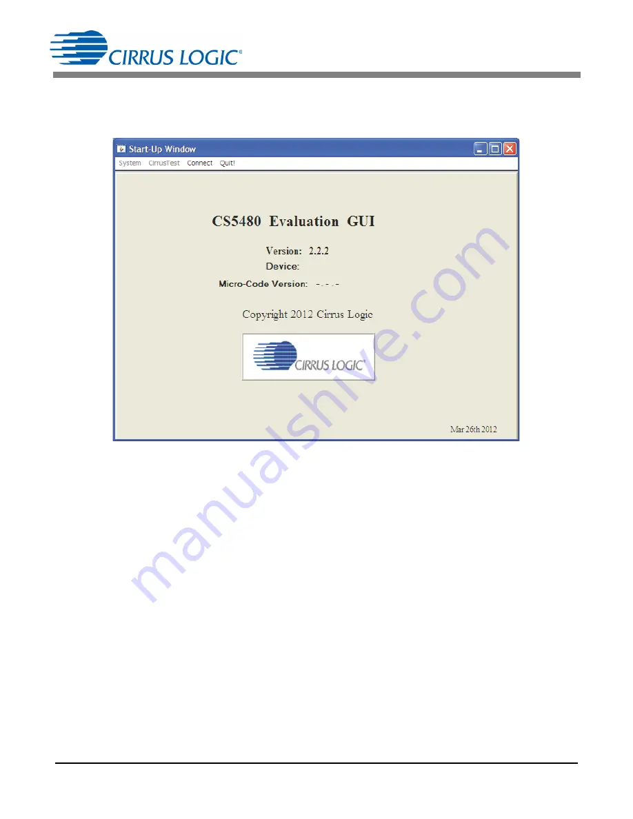
When the software is launched, the start-up window will appear. This window contains information
concerning the software's title, revision number, and copyright date (see Figure 10).
Figure 10. GUI Start-up Window
A menu bar at the top displays four items:
System
,
Cirrus Test
,
Connect
, and
Quit
. Initially
System
and
Cirrus Test
are disabled. After establishing a link to a data source, the
System
and
Cirrus Test
items will
become available.
2.4
Connect
Menu
The
Connect
menu allows the user to establish a USB communication link with CDB5480U board. After
the USB communication has been established, the CS5480 serial port configuration needs to be entered
according to the position of jumper J16. Connecting to the CDB5480 is a two-step process:
1.
Use the “USB Item” to connect to the MCU.
2. Use the “CS5480 Serial Port Config Item” to connect the MCU to the CS5480.
2.4.1
USB Item
In the
Connect
menu, the USB item allows the user to establish USB communication. If the USB item in
the
Connect
menu is selected, the evaluation software will poll the C8051F342 microcontroller, verifying
the serial communication link is ready. When the Connect to the CDB board popup window appears (see
Figure 11), the user should reset the CDB5480 using switch (S1) on the board, wait for Windows to
Summary of Contents for CDB5480U
Page 40: ...CDB5480U 40 DS893DB5 APPENDIX B SCHEMATICS Figure 32 Schematic Analog Inputs ...
Page 43: ...CDB5480U DS893DB5 43 APPENDIX C LAYER PLOTS Figure 35 Top Silkscreen ...
Page 44: ...CDB5480U 44 DS893DB5 Figure 36 Top Routing ...
Page 45: ...CDB5480U DS893DB5 45 Figure 37 Bottom Routing ...
Page 46: ...CDB5480U 46 DS893DB5 Figure 38 Solder Paste Mask ...


