O
AC
E3 0
60
1.
04
e
n-
G
B
, I
D
-N
o.
: 1
76
-6
22
/0
www.imo.se
4
9
Measures shall be provided to avoid
accidental contact with the outer magnetic
rotor.
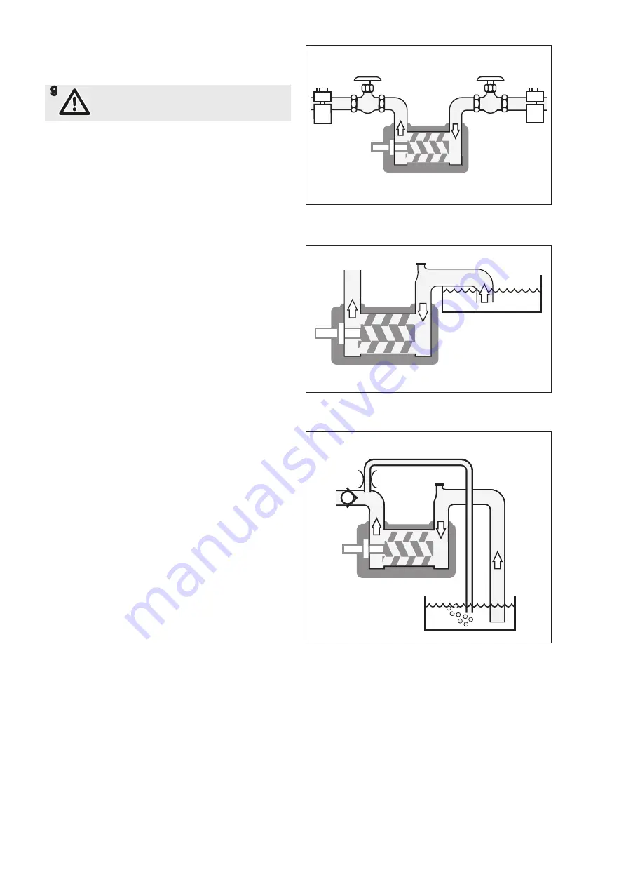
Pipe connections
The pipe work shall be installed and supported so that
no pipe stresses are transfered to the pump body.
The pipe work should be tight in order to avoid leakage
and infiltration of foreign particles and/or air.
Shut off valves should be installed in both suction and
discharge pipes, so that the pump can be hydraulically
isolated.
Suction line
The suction pipe should be designed so that the total
pressure drop, measured at the pump inlet flange, does
not exceed the suction capability of the pump.
Make a proper calculation of the suction line including
components such as valves, strainer, pipe bends etc.
Generally, the pressure drop in the suction line should
be as low as possible, which is achieved if the suction
pipe is short, straight and has a suitable diameter.
The velocity in the suction line should be kept in the
range 0.5 1.2 m/s. For L.O. circulating systems, we
recommend to keep it as low as possible.
These recommendations may imply piping dimesions,
deviations from the actual port sizes, dependent on
pump speed and other duty conditions. To facilitate
priming at startup, the suction line should have a
minimum internal volume, not bigger than what can be
displaced (oil filled) by the pump within 30 seconds.
The suction line must be equipped with a port that al
lows filling the pump before start.
Discharge line
The discharge line should be dimensioned to keep the
velocity in the range 1 3 m/s.
Deaeration
In installations with negative suction head, where the
pump might be started against a pressurized system, a
deaeration pipe with an orifice (2-3 mm recom mended)
has to be installed. The deaeration pipe should be con
nected to the outlet pipe’s highest point.
This must also be installed when the pump is used as
an standby pump.
Fig. 3 Pipe connection
Fig. 4 Suction line
Fig. 5 Dearation


