27
Installation
B
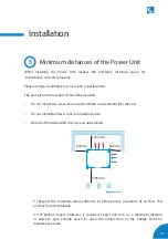
Minimum distances of the Power Unit
When installing the Power Unit, respect the minimum distances space for
maintenance and safety reasons.
Please comply accordingly to your country specifications.
The next picture shows how it should be installed.
•
Do not install near areas where water or fluids can penetrate into the unit.
•
Do not install the Power Unit on unstable terrain.
•
Note that frontal and left side have air outlet/inlets.
(*) Respect the minimum lateral distance to allow proper circulation of air flow. This
unit has forced ventilation.
(**) If Bollard Impact Protector is installed, keep 1200 mm as a minimum distance
in order to give enough space to open the frontal door of the Charge Point for
maintenance tasks.
1200mm
1200mm
800mm
800mm
Summary of Contents for Raption 150 Series
Page 1: ...Installation Manual Raption 150 Series ...
Page 2: ......
Page 4: ......
Page 7: ...03 ...
Page 20: ...16 Raption 150 Series Installation Manual Power Unit front door Power input supply ...
Page 21: ...17 Power Unit rear door Output wiring to Dispenser ...
Page 27: ...23 1 2 3 4 ...
Page 34: ...30 Raption 150 Series Installation Manual E Dispenser template dimensions 435 300 70 ...
Page 35: ...31 400 165 280 310 ...
Page 37: ...33 0 1920 ...
Page 51: ...47 CCS CCS CHA CHA 3 ...
Page 53: ...49 PE DC 2 L N PE ETHERNET CABLE 2 1 3 DC 1 2 2 Wiring connection for the Dispenser Scheme ...
Page 55: ...51 L1 N PE ETHERNET 1 2 ...
Page 56: ...52 Raption 150 Series Installation Manual CCS CCS 3 ...
Page 57: ...53 CHA PE CHA 3 ...
Page 59: ...55 ...
Page 65: ...61 ...


