User’s Guide
21020285 D
Chapter 3 Hardware Installation
Step 3: Board Insertion
Page 3 - 11
Step 3: Board
Insertion
Although the VMEbus Specification has very precise mechanical and electrical
requirements for the subrack, it still leaves room for variance in the design of
the system enclosure. You will need to examine the enclosure that you will be
working with to determine how to get access to the subrack.
General Steps
In most cases you will need to follow these steps to insert the board:
1.
Remove power from the system.
2.
Remove as much of the enclosure shell as is necessary to adequately
access the VMEbus subrack.
3.
Choose a free double-height slot for the RF3880.
4.
Remove bus grant arbitration and interrupt acknowledge jumpers from
backplane. You will need to remove the four Bus Grant jumpers, and
the Interrupt Acknowledge daisy-chain jumper from the slot chosen for
the RF3880. These jumpers must be installed only for empty slots.
5.
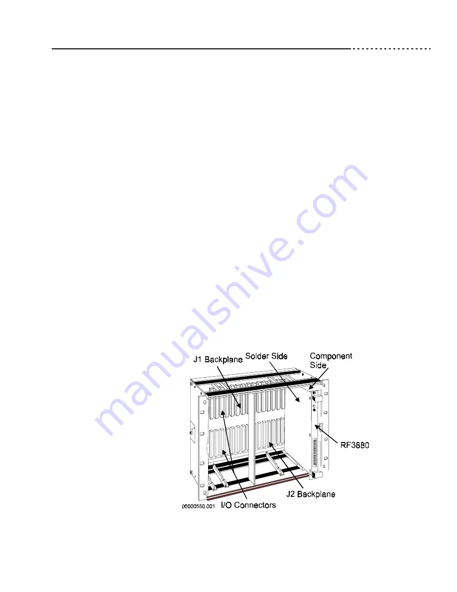
Align the RF3880 with the board guides on the subrack for the slot you
have chosen. Be sure the orientation is correct. (If J1 on the subrack
backplane is up, the component side of the board should face right.)
6.
Slide the board forward and firmly press into the J1 and J2 connectors
on the backplane. You should feel it give slightly as you press inward.
7.
If your system subrack accommodates them, fasten the small screws on
the RF3880 into the subrack. You will need a small flat bladed
screwdriver.
The illustration on the next page demonstrates insertion of the RF3880 into a
VMEbus subrack. Do not reinstall the enclosure panels yet. You will need to
observe the faceplate LEDs in the next step.
Figure 12 Inserting the RF3880
Summary of Contents for Rimfire 3880
Page 1: ...Rimfire 3880 SCSI Host Bus Adapter User s Guide Ciprico Inc Publication No 21020285 D...
Page 2: ......
Page 4: ...21020285 D User s Guide...
Page 25: ...2 H a r d w a r e E s s e n t i a l s...
Page 42: ...21020285 D User s Guide Chapter 2 Hardware Essentials Page 2 18 Descriptions of Port Usage...
Page 43: ...3 H a r d w a r e I n s t a l l a t i o n...
Page 59: ...4 C o m m a n d O p e r a t i o n...
Page 85: ...5 I n i t i a t o r M o d e P a s s t h r o u g h C o m m a n d s...
Page 103: ...6 T a r g e t M o d e P a s s t h r o u g h C o m m a n d s...
Page 125: ...7 B o a r d c o n t r o l C o m m a n d s...
Page 175: ...8 D e t a i l s o f U s a g e...
Page 193: ...A E r r o r C o d e s...
Page 201: ...B C a b l e s a n d C o n n e c t o r s...
Page 206: ...21020285 D User s Guide Appendix B Cables and Connectors Page B 6 VMEbus Connector Pinouts...
Page 207: ...C S p e c i f i c a t i o n s...
Page 210: ...21020285 D User s Guide Appendix C Specifications Page C 4 Specifications...
Page 211: ...D D e f a u l t s...
Page 216: ...21020285 D User s Guide Appendix D Defaults Page D 6 HardwareDefaults...
Page 217: ...E D e s i g n D i f f e r e n c e s...
Page 229: ......
Page 230: ...21020285 D...


