


DC-1200 Series | User Manual
42
3.11
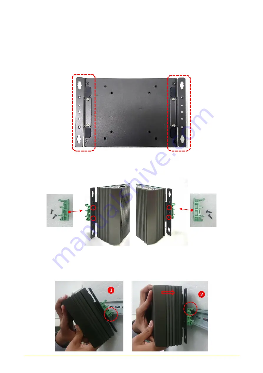
DIN-Rail Mount
DC-1200 series offers DIN-Rail Mount that customer can install system on the DIN Rail.
1.
The mounting holes are at the bottom side of system. Use provided 4 screws to fasten
the bracket with each side on system together.
2.
Fasten 2 DIN rail mounting clips to mounting brackets on both sides with provided 4
screws as illustrated.
3.
Clip the system into DIN rail as illustrated by the following steps. (1) Have lower end of
mounting clip snaps into the DIN rail. (2) Press the system toward to have upper end of
mounting clip snaps into the other side of DIN rail.
Summary of Contents for DC-1200 Series
Page 11: ...DC 1200 Series User Manual 11 Chapter 1 Product Introductions ...
Page 17: ...DC 1200 Series User Manual 17 1 7 Mechanical Dimension Unit mm ...
Page 18: ...DC 1200 Series User Manual 18 Chapter 2 Switches Connectors ...
Page 19: ...DC 1200 Series User Manual 19 2 1 Location of Switches and Connectors 2 1 1 Top View ...
Page 20: ...DC 1200 Series User Manual 20 2 1 2 Bottom View ...
Page 28: ...DC 1200 Series User Manual 28 Chapter 3 System Setup ...
Page 43: ...DC 1200 Series User Manual 43 Chapter 4 BIOS Setup ...
Page 61: ...DC 1200 Series User Manual 61 Chapter 5 Product Application For CMI DIO03 only ...
Page 64: ...DC 1200 Series User Manual 64 ...
Page 65: ...DC 1200 Series User Manual 65 ...
Page 76: ...DC 1200 Series User Manual 76 Reference Input Circuit Reference Output Circuit ...