24
Plus 42 - 45 - 50 - 55 - 55S - 55E
11-2000
00027
00080
5.2 - MOUNTING OF THE TRANSMISSION SHAFT
UTILISE TRANSMISSION SHAFTS WITH CE CERTIFICATION.
OBSERVE THE REGULATIONS CONTAINED IN THE USE AND MAINTENANCE BOO-
KLET PROVIDED BY THE SHAFT MANUFACTURER.
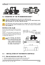
The transmission shaft must work with the 2 COAXIAL drive outlets (Pdp) or, should
this not be possible, with the PARALLEL axles. In this case the angle of the joint MUST
NOT EXCEED 15°.
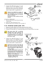
Definition of the length
Set the 2 drive outlets (PdP) perfectly on the same
axis and measure the distance “D” between their
grooves.
Length “L” of the transmission shaft (refer to the
Picture) to be deployed, measured between the
2 stopping pawls and with joint closed, must be 25
mm lesser than distance “D”.
The mounting, the disassem-
bly or possible other interven-
tions on the transmission shaft
must be carried out with the
engine switched off and with
the starter key removed from
the tractor’s control panel.
15° MAX
D
L = D - 25
00081
00082
00083
5.3 - INSTALLATION OF THE REMOTE CONTROLS
5.3.1 - Manual distributor with 2 taps - P10
1 – Mount the securing bracket on the tractor within the driver’s reach.
2 – Insert the distributor’s bayonet support in the securing bracket.

