CIM ME2000S Operator'S Manual Download Page 25

OPERATOR MANUAL 


4. 

Installation 

21


4.3


Electrical connection 

The installation of the embosser 

ME2000s

 can be easily carried out by accessing the various connections 

plugs, located on the rear panel. 
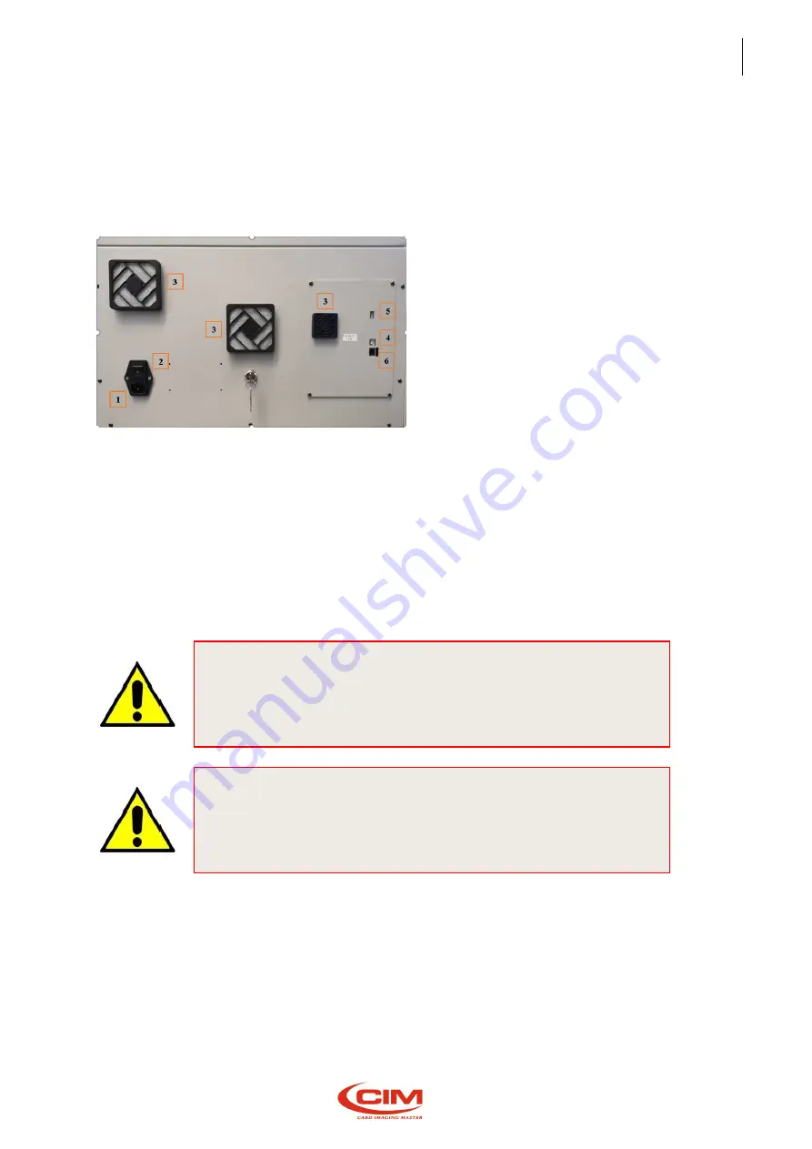
 

BACK PANEL 


1.


SOCKET PA 80 FOR MAIN CABLE 

2.


POWER SWITCH AND FUSE 

3.


VENTILATION FILTER GRIDS 

4.


USB PLUG TYPE B 

5.


USB PLUG TYPE A 

6.


ETHERNET PLUG  

7.


COVER DISABLE KEY  


Proceed as indicated below:  


Connect the USB TYPE B cable (Optional) between the Computer and the  Embosser in case you 
use the embosser in ON-LINE mode. 


Check that the main AC Voltage corresponds to the value indicated in the  plate. 
Before proceeding, note down the information contained in the paragraph  “WARNINGS AND 
INSTALLATION PRECAUTIONS” 


Connect the power cable. Be sure that cable socket is easily accessible. 


4.4


Connection to a computer 

The ME2000s can be supplied with a 2 m long cable (optional) for USB connection.  
If this length is not enough, it is necessary to use an extension cable not longer than 15 meters, 
respecting the corresponding connections 

CAUTION: 

THE SERIAL CABLE MUST BE CONNECTED ONLY WHEN THE MACHINE IS 

OFF. 

CAUTION: 

CONNECT ONLY TO SYSTEMS PROVIDED WITH GROUNDING CIRCUIT 

COMPLIANT WITH THE NATIONAL SYSTEM REGULATIONS 

Summary of Contents for ME2000S

Page 1: ...OPERATOR MANUAL EN ME2000S MO ME2000S EN R1...

Page 2: ...ecifically approved or guaranteed by MF Group CIM division Reproduction Modification complete or partial translation of this manual is strictly forbidden without prior written approval of MF Group CIM...

Page 3: ...d use and limits 8 2 10 Residual risks 9 2 11 Operating precautions and safety regulations 10 2 12 Safety requirements 11 2 13 Operation in technician mode 12 2 14 Symbols present on the machine 13 2...

Page 4: ...es F10 53 5 5 11 Touch calibration F11 54 6 Initial setting 55 6 1 Loader adjustment 56 6 2 Unloader adjustment 57 6 2 1 Unloader ejector adjustment 57 6 2 2 Unloader lift adjustment 57 6 3 Embossing...

Page 5: ...dification or updating of the Manual you receive is added to the text MF Group srl CIM division is not liable for technical or editorial errors or omissions contained herein 1 2 How to keep the manual...

Page 6: ...N TO SYMBOLS AND TO THE INSTRUCTIONS CONTAINED IN THE TEXT NEXT TO THEM Prescription and Indication signs rectangular shape obligation to use the protections indicated on the sign to carry out the ope...

Page 7: ...dy for subsequent use even if the machine has been switched off The METAL EMBOSSER system consists in an embosser unit driven by a personal Computer not supplied connected to a Computer with an USB po...

Page 8: ...S and is useful for their identification It is also meant as an instrument that allows the client to interface with our specialized technicians in the most appropriate and suitable way MAIN COMPONENTS...

Page 9: ...SB keyboard connected optional an LCD touch panel the operating state of the machine the functions settings and the machine settings symbols logos and fonts it is possible to access the various functi...

Page 10: ...BOSSING After picking up the plate the clamps transport it to the printing area placing it under the drum and simultaneously extracting another one At the same time the drum rotates thus taking the ch...

Page 11: ...bility Stationary Applicable standards UL62368 1 2nd Ed IEC 62368 1 IEC EN 55032 2015 IEC EN 55024 2010 A1 2014 IEC EN 61000 3 2 2014 IEC EN 61000 3 3 2013 2 6 Physical environment and operating condi...

Page 12: ...plex 2 OCRB1 Block USA Double Block etc Height 3 12 mm 0 118 0 472 inch Indenting Simplex1 Simplex 2 etc Height 1 4 mm 0 039 0 157 inch Debossing Elite Dog Tag Performance 231 tags per hour based on 5...

Page 13: ...r because moving parts can be reached in case of fault of the top door sensor In order to avoid pain or injury operator shall be informed about moving parts that require attention so that he may keep...

Page 14: ...vent the operator from coming in contact with the mechanical and electrical parts inside the ine Only specialized and authorized operators can access these parts for maintenance and repairs Simple gen...

Page 15: ...e cover open in this case the chanical parts represent a potential danger for the operator s safety if the protection systems are damaged switch off the machine and call for technical support Warning...

Page 16: ...consequences these rules for the use of the machine In case of breakdown service peration in technician mode The authorized technical staff can temporarily disable the safety system associated to the...

Page 17: ...e than one person The net weight is 31 Kg Be extremely careful when moving it CAUTION HIGH VOLTAGE It is forbidden to carry out any work when the machine is under power To replace the mains fuse or to...

Page 18: ...unding system The symbol of the crossed out wheeled bin on the product or on its packaging indicates that it should not be disposed of as a household waste Instead it shall be handed over to the appro...

Page 19: ...OPERATOR MANUAL 2 General information 15 2 16 Declaration of CE Conformity...

Page 20: ...complies with the following European Directives 2014 30 UE 2014 35 UE 2006 42 EC ME2000S complies with the IEC International Standards on Safety of electrical and electronic equipment within the field...

Page 21: ...e check that the packing is intact and not damaged Make sure that the case has not been turned over during transportation Check that the seal on the indicator is not red CAUTION THE EMBOSSER WEIGHS AB...

Page 22: ...he 19mm fork wrench es UNI 6736 which is fixed on top of the machine by on adhesive band Remove the crews from the bottom of the case 2 with the 19 wrenches Having removed the screws the machine can b...

Page 23: ...plied with the embosser in a separate bag are listed below 1 POWER CABLE WITH SCHUKO PLUG CEE VII 1 USB PEN DRIVE CONTAINING THE OPERATOR S MANUAL 2 KEYS TO OPEN THE MACHINE SOFTWARE HARDWARE KEY The...

Page 24: ...them Make sure that the surface on which the machine is placed does not amplify the noise level above the allowed value and that it is sufficiently strong and solid to stand the weight of the machine...

Page 25: ...N LINE mode Check that the main AC Voltage corresponds to the value indicated in the plate Before proceeding note down the information contained in the paragraph WARNINGSAND INSTALLATIONPRECAUTIONS Co...

Page 26: ...sser model Type Machine Type V nom Power Voltage Hz SupplyFrequency Imax Absorbed Current SN Serial Number Made in Italy Year of construction Fuse Rate Rating of the fuse If the supply voltage is more...

Page 27: ...00S Power on and checking After the installation you can get power to the machine turning the main switch ON performs a reset and self test cycle without showing any message on the fter about 20 secon...

Page 28: ...shift at least once a day switch the machine on and when it is in READY condition open the front cover Then check that the machine after any inter put signals an alert situation cover open or pin in i...

Page 29: ...lity to requirements of the metal plates embossers industry The machine allows to set up and perform a job set its options and parameters also verify the functioning of some of its electrical and mech...

Page 30: ...ob Pause the job Stop the job Tag preview Edit the highlighted field 5 Human Machine Interface and related function you will find move through the screens Description Return to Main Menu Back to previ...

Page 31: ...ce or F1 Through the various functions present in the LCD EDIT menu it is possible to produce tags in STAND option provides all those functions necessary to create set up and perform a job The option...

Page 32: ...g field Format name Name of the Format Card type Type of Tag Card material Material not editable Card number Number of Tag to print 01 to 06 Row of text to print to show a preview of the Tag To emboss...

Page 33: ...nction is used to view in advance the tag to be produced and then make possible changes or F2 retrieves the active selected format used to display the contents of the fields and their To exit Preview...

Page 34: ...and remove print formats or F3 formats have the same structure and layout of a tag defining the position of the required text fields Each field is provided with specific settings such as coordinates s...

Page 35: ...ows to remove a format previously introduced If the format to be removed is the active one it will be necessary to enable another one to print in standalone mode view and modify an existing format bot...

Page 36: ...to a distance of 0 36 mm The following chart can be used to assign the value of the spacing between the characters Spacing Table Constant Characters inch Characters mm 05 14 4 5 56 06 11 7 4 61 07 10...

Page 37: ...red manually or loaded from a data base Protected ield with fixed text where the contents cannot be modified Counter ield with counter function The number of the counters us assigned when closing the...

Page 38: ...sible to use a fixed job in the machine memory OPTIONAL Switching off the machine implies deleting the print queue and making the log file saving impossible Comma Separator Value data files can be gen...

Page 39: ...OPERATOR MANUAL 5 Human Machine Interface 35...

Page 40: ...enerate and save only on a USB FLASH PEN DRIVE a log file ess or F5 The file contains the information concerning the processed tags both the produced ones and the rejected ones and the possible errors...

Page 41: ...lized technical staff or at least under their supervision For this reason it is protected with a password SETUP menu consists of seven main functions CONFIGURATION F1 LAN F2 MECHANICAL PARAMETERS F3 P...

Page 42: ...Path It sets the way to drive the axes by punch by line or according the path optimization algorithm Hide protected data It does not display the data of protected fields When leaving the page the sav...

Page 43: ...If not the message Not valid will appear 5 Human Machine Interface The option allows to set the standard communication parameters of the embosser to connect it to a computer and respect the specificat...

Page 44: ...ICAL RED ALERT TAG plates Warning assigning non correct values causes the malfunctioning of the embosser and possible damages to some of its components therefore we strongly recommend that only sp sta...

Page 45: ...ine From SETUP menu press key or F4 This guarantees flexibility and adaptability of the embosser to the various interfacing requirements of the user Active protocol it allows to select the protocol to...

Page 46: ...ion 5 Human Machine Interface Embossing wheel F5 It indicates which drum configuration and characters layout are installed on the machine or F5 The characters setup in the drum layout must match perfe...

Page 47: ...e for each character if punch adjustment is selected 5 Human Machine Interface to set position of characters on the drum to adjust pressure for each character if punch adjustment is OPERATOR MANUAL Hu...

Page 48: ...ifferent shape of tag that the machine can produce or F6 reate a new configuration Delete an existing configuration Edit a new configuration Top Translation Table F7 The table shows the association of...

Page 49: ...ressing F1 Assign new value and press OK You can use also the external keyboard if connected 5 Human Machine Interface it enables disable the TTT function to convert the input data characters with the...

Page 50: ...onfig locally F8 It allows to save on the machine s memory all parameters and setting From SETUP menu press or F8 Automatically start the procedure that save all the data on the local memory ATTENTION...

Page 51: ...a password PAGE 1 PAGE 2 Use arrows to switch pages 5 Human Machine Interface F3 The SERVICE option contains a series of functions for the analysis and updating of the embosser firmware and it is mea...

Page 52: ...tions 1 LANGUAGE F1 2 CARD TEST F2 3 OPERATIONAL MODE F3 4 SYSTEM INFORMATION F4 5 COUNTER F5 6 TEST F6 7 SAVE CONFIG IN USB F7 8 UPDATE SOFTWARE CPU1 F8 9 DISABLE ENABLE COVER F9 10 ERRORS CODE F10 1...

Page 53: ...menu press To select language press Languages available English Spanish Italian 5 Human Machine Interface The option allows to choose the language that will be used to display all the messages and men...

Page 54: ...This option allows to set some operating modes during the stages of the tag embossing process There are three working modes CONTINUOUS PAUSE WITHOUT CARD and all their combinations This option is usua...

Page 55: ...e number of tags produced from the last reset Total counter displays the total number of tags produced by the embosser since its installation This option allows to perform some tests on several compon...

Page 56: ...mware and the setup file of one of the CPU boards installed on the machine CPU This option is only for the specialized technical staff or for authorized people and it is protected by password The care...

Page 57: ...Interface F10 This option allows to display the list of the codes of the errors that can occur in the embosser and it makes the operator understand the possible cause that generated the error ERROR ME...

Page 58: ...red on the CPU In case of CPU replacement it may be necessary to procedure 5 Human Machine Interface Touch calibration F11 to calibrate the display LCD touch screen or F11 or ESC Touch the cross that...

Page 59: ...er Unloader Embosser Open the front panel after input the key supplied the METAL EMBOSSER as shown in figure below 1 PLATES LOADER 2 PUNCH DEVICES 3 PLATES UNLOADER The machine should be switched off...

Page 60: ...ont cover Loosen the black knobs 1 on the right side of the Loader Bring the right support closer to the plate to be embossed leaving a tolerance of about 1mm and then tighten the knobs Loosen the win...

Page 61: ...e second eject the plates out of the Embosser 6 2 1 Unloader ejector adjustment Loosen the black knob 1 Place a plate on the ejector plane Shift the bracket towards the plate Leave a gap of 1 millimet...

Page 62: ...s necessary to loosen the nut 1 which blocks the knob 2 This is done with a 13mm wrenc Next observing the notches an the knob turn the knob a few degrees in a clockwise direction Now tighten the nut T...

Page 63: ...d IP Set up Please refer to your network administrator to configure the machine with right IP address When the machine is connected to internal network through ethernet cable or WiFi it s possible to...

Page 64: ...PERATOR MANUAL 7 Internet of Things 60 7 3 1 Information On this page there are all the info related to hardware and software of the machine 7 3 2 Network Here you can check all the network parameters...

Page 65: ...AL 7 Internet of Things 61 7 3 3 Date and time 7 3 4 Update software With this function it s possible update the software when available a new release 7 3 5 Users management Here it s possible check t...

Page 66: ...ergency button pressed Emergency button pressed Twist to release the button Formats file save error Software internal error Please contact Technical Assistance Generic error Software internal error Pl...

Page 67: ...Properties file save error Software internal error Security sensor active Loader area busy Remove objects from loader area Tag presence sensor Tag presence photocell active Unloader full The unloader...

Page 68: ...ans located in the rear part of the machine IF THE FILTERS ARE WASHED WITH WATER THEY MUST BE DRIED IF THEY ARE WET OR DAMP THEY CAN CAUSE SHORT CIRCUITS AND IRREVERSIBLE DAMAGES TO THE MACHINE Every...

Page 69: ...a viscosity of about 60 68 mm2 sec at 40 Oil the holes of the plate loader group shown in the figure About every 6 months a greasing of the internal mechanical parts is necessary However it can be do...

Page 70: ...he jaws is a little difficult but with a long spout on the oiler it can be done Lubricate the cams 1 UNLOADER LIFTER Oil with Vaseline the unloader lifter s vertical guide 1 LUBRICATING THE MOTOR PULL...

Page 71: ...OPERATOR MANUAL 9 Maintenance 67 At the end of every maintenance work switch the machine on again and check that when opening the front panel the machine stops any operation in progress...

Page 72: ...0 F 1 305 639 3060 techsupport www cim usa com MF GROUP S r l CIM Via O Serra 2 40012 Lippo di Calderara di Reno BO Italy T 39 051 6465 011 F 39 051 6465 012 cimtech cimitaly it www cimitaly it CIM TR...

Reviews: