CIGWELD 250i Transmig Service Manual Download Page 115

REPLACEMENT PARTS 


TRANSMIG 250i

Manual 0-5188  

8-1 

REPLACEMENT PARTS

SECTION 8: REPLACEMENT PARTS

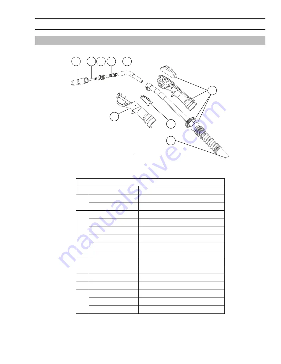
8.01  TWECO FUSION 250 MIG TORCH

A-10341

2

1

4

3

7

55

7

6

7

8

Figure 8-1

TWECO FUSION MIG TORCH PARTS

ITEM

PART NO.

DESCRIPTION

1

OTW22/50

Nozzle 13mm

OTW22/62

Nozzle 16mm

2

OTW14/23

Contact Tip 0.6mm

OTW14/30

Contact Tip 0.8mm

OTW14/35

Contact Tip 0.9mm

OTW14/40

Contact Tip 1.0mm

OTW14/45

Contact Tip 1.2mm

3

OTW32

Insulator

4

OTW52

Gas Diffuser

5

62J-45S

Conductor Tube, 45 Degree

6

W7005001

Trigger Assembly

7

W7005000

Handle Mouldings

8

OTW42/3035

Liner 0.8-0.9mm Hard Wire

OTW42N/3545

Liner 0.9-1.2mm Soft Wire

OTW42/4045

Liner 1.0-1.2mm Hard Wire

Table 8-1

Summary of Contents for 250i Transmig

Page 1: ...300 240 PFC 250i Service Manual Revision AA Issue Date September 14 2012 Manual No 0 5188 Operating Features TRANSMIG MULTI PROCESS WELDING INVERTER...

Page 2: ...contained in this manual Due to our constant effort to bring you the best products we may make an improvement that does not get reflected in the manual If you are ever in doubt about what you see or r...

Page 3: ...West Lebanon New Hampshire USA 03784 603 298 5711 www cigweld com Copyright 2012 by Victor Technologies All rights reserved Reproduction of this work in whole or in part without written permission of...

Page 4: ...der Controls Indicators and Features 3 15 3 09 Optional Wire Feeder Set Up MIG GMAW Welding with Gas Shielded MIG Wire 3 16 3 10 Optional Wire Feeder Set up for MIG FCAW Welding with Gasless MIG Wire...

Page 5: ...Current Amperage Calibration 6 8 6 07 Output Voltage Calibration 6 10 6 08 Wire Speed Calibration 6 11 6 09 Case Removal 6 14 6 10 Visually Inspect 6 14 6 11 Preliminary check of the main inverter bo...

Page 6: ...APPENDIX 1 OPTIONS AND ACCESSORIES A 1 APPENDIX 2 TRANSMIG 250i CIRCUIT DIAGRAM A 2 CIGWELD LIMITED WARRANTY RC 2 CIGWELD TERMS OF WARRANTY APRIL 2012 RC 3 WARRANTY SCHEDULE APRIL 2010 RC 4...

Page 7: ...od electrical earth ground 11 DO NOT touch electrode while in contact with the work ground circuit 12 Use only well maintained equipment Repair or replace damaged parts at once 13 In confined spaces o...

Page 8: ...imate Range of Welding Current in Amps Minimum Shade Number of Filter s Manual Metal Arc Welding covered electrodes MMAW Less than or equal to 100 8 100 to 200 10 200 to 300 11 300 to 400 12 Greater t...

Page 9: ...s overheating or fire 1 Protect yourself and others from flying sparks and hot metal 2 Do NOT weld where flying sparks can strike flammable material 3 Remove all flammables within 10M of the welding a...

Page 10: ...ects and in some cases cancer California Health Safety code Sec 25249 5 et seq NOTE Considerations About Welding And The Effects of Low Frequency Electric and Magnetic Fields The following is a quotat...

Page 11: ...ompressed Gas Association 1235 Jef ferson Davis Highway Suite 501 Arlington VA 22202 Code for Safety in Welding and Cutting CSA Standard W117 2 from Canadian Standards Association Standards Sales 178...

Page 12: ...Directive National Standard and Technical Specifications The product is designed and manufactured to a number of standards and technical requirements among them are IEC 60974 10 applicable to Industri...

Page 13: ...ption of the parts in error Move the equipment to the installation site before un crating the unit Use care to avoid damaging the equip ment when using bars hammers etc to un crate the unit 2 01 How t...

Page 14: ...uit Breaker AC Auxiliary Power Remote Duty Cycle Percentage Amperage Voltage Hertz cycles sec Frequency Negative Positive Direct Current DC Protective Earth Ground Line Line Connection Auxiliary Power...

Page 15: ...n con tained herein when installed operated maintained and repaired in accordance with the instructions provided This equipment must be checked periodically Defective equipment including welding leads...

Page 16: ...er Source Gas Hose 3M Operating Manual Drive Roll V Groove 0 9 1 2mm Fitted Pressure Roll 0 6 1 2mm Solid Wire Fitted Outlet Guide 0 9 1 2mm Fitted Transmig 250i MIG Plant Asia Part number W1003250M T...

Page 17: ...ding time out of every 10 minute period 40 of 10 minutes is 4 minutes During the other 6 minutes of the 10 minute period the Welding Power Source must idle and be allowed to cool Art A 10315 Duty Cycl...

Page 18: ...ps Welding Current Range LIFT TIG Mode 5 235 Amps 5 300 Amps Welding Current Range STICK Mode 20 170 Amps 20 230 Amps Effective Input Current I1eff 15 Amps 22 4 Amps Maximum Input Current I1max 23 7 A...

Page 19: ...ion Be sure to locate the welder according to the following guidelines A In areas free from moisture and dust B Ambient temperature between 0 C to 40 C C In areas free from oil steam and corrosive gas...

Page 20: ...disconnect input power employing lockout tagging procedures Lock out tagging procedures consist of padlocking line disconnect switch in open position removing fuses from fuse box or shutting OFF and r...

Page 21: ...nsmitters and receivers 3 Computer and other control equipment 4 Safety critical equipment e g guarding of industrial equipment 5 The health of people around e g the use of pace makers and hearing aid...

Page 22: ...tances Care should be taken to prevent the earthing of the work piece increasing the risk of injury to users or damage to other electrical equipment Where necessary the connection of the work piece to...

Page 23: ...on and welding is being performed the presence of dangerous voltage may be present at the electrode 2 Power Indicator The green power indicator will be illuminated when the welder is turned ON and in...

Page 24: ...usted value as the knob is turned and will automatically revert back to showing the weld current measurements when the knob is not being turned 8 Right Knob Multifunction Control MIG Voltage Arc Contr...

Page 25: ...on welding the amperage meter will display a pre set preview value in both STICK and LIFT TIG modes This value can be adjusted by varying the Left Knob Control No 7 When welding this digital meter wil...

Page 26: ...MIG Torch nut clockwise to secure in position To remove the MIG Torch simply reverse these directions 12 Remote Control Socket The 8 pin Remote Control Socket is used to connect remote control device...

Page 27: ...rch Trigger Switch E Wire Speed Pot Voltage Pot CW 10K ohm F Wiper Arm Speed Pot G Torch Trigger Switch Solenoid H Wire Speed Pot Voltage Pot ACW I Solenoid J Peripheral Program Resistor Table 3 4 14...

Page 28: ...ed Features Details General Operation LIFT TIG Select the weld process Control No 4 you wish to view Advanced Features for Then press and release the Advanced Features button Control No 6 to enter or...

Page 29: ...s MIG GMAW FCAW Mode Advanced Features Menu Map RUN IN POST FLOW BURN BACK WIRE SHRP Advanced Menu MIG Mode Wire Feed Speed ARC TYPE MIG CNTL PRE FLOW SPOT STCH DWEL TIME ON OFF STCH TIME AUTO CV Adva...

Page 30: ...xt weld Spot SPOT OFF OFF ON Spot is used to weld two thin plates together at a desired location by melting the top bottom plates together to form a nugget between them The weld time is set by the Spo...

Page 31: ...ng Mode FACT DFLT Left Knob Selection Right Knob Selection Left Display Right Display HR TIG CNTL DOWN SLPE Advanced Menu LIFT TIG Options or Range Press Advanced Button to Exit to Welding Mode 0 0 5...

Page 32: ...The number displayed is in hours and read only It will rollover to 0 once 10 000 hours have been reached Restore Factory Defaults FACT DFLT NO NO YES When YES is selected all the user adjustable val...

Page 33: ...res The optional 2RT Wirefeeder is designed to be used with the Transmig 250i Select MIG Process and REMT in Ad vanced Features to enable the controls on this wirefeeder There are two controls on the...

Page 34: ...ith an 8M interconnection cable assembly to connect from the back of the 2RT to the front of the 250i welding power source Connect the MIG Torch to the front of the 2RT as you would to the front of th...

Page 35: ...terminal on the front of the 250i The 2RT Wire Feeder is fitted with an 8M interconnection cable assembly to connect from the back of the 2RT to the front of the 250i welding power source Front View...

Page 36: ...tre screw in the cover and open the side cover to the wire spool so you can see the 3 holes that will need to align with the mounting studs from the roll cage 4 Carefully lift the unit and maneuver in...

Page 37: ...t base section to the upright rear section with the 3 screws provided NOTE If attached the optional roll cage must be removed before mounting to the Welding Trolley as the same mounting holes are used...

Page 38: ...Trolley and lock securely to the Trolley cylinder bracket with the chain provided If this arrangement is not used then ensure that the gas cylinder is secured to a building pillar wall bracket or othe...

Page 39: ...ht clockwise Refer to Figure 3 17 Attach MIG Torch Turn locking ring to the right Art A 10338 Figure 3 17 Mount MIG Torch Cable to Adapter Socket 2 If equipped align the keyways of the MIG Torch Switc...

Page 40: ...n the spool alignment pin on the hub with the mating hole in the wire spool 3 Replace the Wire Spool Hub Retaining Clip in the set of holes closest to the spool NOTE The Hub tension has been pre adjus...

Page 41: ...lign the spool alignment pin on the hub with the mating hole in the wire spool 3 Replace the Wire Spool Hub Retaining Clip in the set of holes closest to the spool NOTE The Wire Wheel Brake has been p...

Page 42: ...d over the Feedroll Make certain the proper groove is being used Second part of Figure 3 20 4 Pass the MIG wire over the drive roll groove through the outlet guide and out past the MIG Torch Adaptor T...

Page 43: ...E Genuine TWECO contact tips and liners should be used Many non genuine liners use inferior materials which can cause wire feed problems 3 18 Feed Roller Alignment The bottom Feed Roll is adjustable i...

Page 44: ...ved feed rolls have their wire size or range stamped on the side of the roll On rolls with different size grooves the outer visible when installed stamped wire size indicates the groove in use Refer t...

Page 45: ...uides Output Wire Guide With the MIG Torch removed loosen the adapter nut This will aid with alignment Install the output wire guide the longer one by inserting the conical end part way into the Euro...

Page 46: ...ll cause rapid wear of mechanical wire feed parts over heating of electrical componentry and possibly an increased incidence of wire Burnback into the contact tip NOTE Correct adjustment will result i...

Page 47: ...releasing gas in the regulator high and low pressure chambers 4 Do NOT use the regulator as a control valve When downstream equipment is not in use for extended periods of time shut OFF the gas at the...

Page 48: ...ned for a particular gas or gases to a cylinder containing any other gas 3 Connect the regulator inlet connection to cylinder or pipeline and tighten it firmly but not excessively with a suitable span...

Page 49: ...down stream valve Bleed welding grade shielding gas into a well ventilated area and away from any ignition source Turn adjusting screw counterclockwise until the required flow rate is indicated on th...

Page 50: ...wer Source 3 Connect the MIG Torch Polarity Lead to the positive welding terminal If in doubt consult the MIG electrode wire manufacturer Welding current flows from the Power Source via heavy duty bay...

Page 51: ...pending on the type of wire you will be using the MIG Torch polarity may need to be switched Follow the wire manufacturers recommendation 3 24 Set up for MIG FCAW Welding with Gasless MIG Wire The Tra...

Page 52: ...t required for welding Otherwise fit the welding grade shielding gas regulator flow gauge to the shielding gas cylinder refer to Section 3 22 then connect the shielding gas hose from the rear of the p...

Page 53: ...ine hose to the proper shielding gas source Refer to Figure 3 32 4 Be sure the gas valve on the TIG Torch is closed and slowly open the Argon Cylinder Valve to the fully open position 5 Connect the wo...

Page 54: ...al Metal Arc Welding MMAW WARNING Before any welding is to begin be sure to wear all appropriate and recommended safety equipment NOTE The following set up is known as DC Electrode Positive or reverse...

Page 55: ...trol Knob to the desired amperage 5 Install a stick electrode in the electrode holder 6 You are now ready to begin Stick Welding NOTE Gently strike the electrode on the work piece to generate a weldin...

Page 56: ...TRANSMIG 250i INSTALLATION SETUP INSTALLATION SETUP 3 38 Manual 0 5188 Notes...

Page 57: ...lding process which fuses together the parts to be welded by heating them with an arc between a continu ous flux filled electrode wire and the work Shielding is obtained through decomposition of the f...

Page 58: ...welding variables in short arc welding of 0 6mm to 6 4mm mild sheet or plate The applied techniques and end results in the GMAW process are controlled by these variables Preselected Variables Presele...

Page 59: ...e some pieces of 1 5mm or 2 0mm mild steel plate 150 x 150mm Use 0 8mm flux cored gasless wire or a solid wire with shielding gas Setting of the Power Source Power source and Wirefeeder setting requir...

Page 60: ...ing arc to dirt on the work piece surface Porosity can be reduced by checking the following points FAULT CAUSE 1 Shielding gas cylinder contents and flow meter Ensure that the shielding gas cylinder i...

Page 61: ...ed to the pressure roller adjuster B Swarf can also be produced by the wire passing through an incorrect feed roller groove shape or size C Swarf is fed into the conduit liner where it accumu lates th...

Page 62: ...the wirespeed control B Wire is wandering B Replace contact tip C Incorrect shielding gas C Check shielding gas D Insufficient or excessive heat input D Adjust the wirespeed control or the voltage co...

Page 63: ...r normal strength 500 MPa steels and Alloycraft range for higher strength steels B Austenitic manganese steels The effect on manganese steel of slow cooling from high temperatures is to embrittle it F...

Page 64: ...on Fillet Weld Joint Preparations In many cases it will be possible to weld steel sections without any special preparation For heavier sections and for repair work on castings etc it will be necessary...

Page 65: ...he work either directly or through the work table For light gauge material always clamp the work lead directly to the job otherwise a poor circuit will probably result The Welder Place yourself in a c...

Page 66: ...ck your next concern is to maintain it and this requires moving the electrode tip towards the molten pool at the same rate as it is melting away At the same time the electrode has to move along the pl...

Page 67: ...5 from the vertical Some electrodes require to be sloped about 20 away from the perpendicular position to prevent slag from running ahead of the weld Refer to Figure 4 23 Do not attempt to build up mu...

Page 68: ...forms of welding In many cases it is so small that it is barely perceptible but in other cases allowance has to be made before welding commences for the distortion that will subsequently occur The st...

Page 69: ...y be reduced by selecting a welding sequence which will distribute the stresses suitably so that they tend to cancel each other out See Fig ures 4 30 through 4 33 for various weld sequences Choice of...

Page 70: ...lock Sequence The spaces between the welds are filled in when the welds are cool 2 3 Figure 4 34 Welding Sequence Art A 07711_AB 4 3 2 1 Figure 4 35 Step back Sequence Art A 07428_AB Figure 4 36 Chain...

Page 71: ...mm 2 5 kg 2 5 kg 2 5 kg 611602 611603 611604 Stainless Steel type for 19Cr 10Ni stainless grades including 201 202 301 302 303 304 304L 305 308 etc Satincrome 309Mo 17 2 5mm 3 2mm 4 0mm 2 5 kg 2 5 kg...

Page 72: ...Non metallic particles may be trapped in undercut from previous run A If a bad undercut is present clean slag out and cover with a run from a smaller gauge electrode B Joint preparation too restricted...

Page 73: ...ave to allow weld metal buildup G Power source is set for MIG GMAW welding G Set power source to STICK MMAW mode 5 Portions of the weld run do not fuse to the surface of the metal or edge of the joint...

Page 74: ...e circumstances depending on the welding application Welds Made With or Without Addition of Filler Metal Work Piece Can Be Any Commercial Metal Gas Cup Either Ceramic High lmpact or Water Cooled Metal...

Page 75: ...d their alloys Longer life More stable arc Easier starting Wider current range Narrower more concentrated arc Grey Table 4 8 NOTE The Transmig 250i Inverter is not suited for AC Tig welding TIG Weldin...

Page 76: ...mm 7 Butt Corner Lap Fillet 3 2mm 80 100 90 115 65 85 90 110 1 6mm 2 4mm 7 Butt Corner Lap Fillet 4 8mm 115 135 140 165 100 125 125 150 2 4mm 3 2mm 10 Butt Corner Lap Fillet 6 4mm 160 175 170 200 135...

Page 77: ...vel speed 5 Uneven leg length in fillet joint Wrong placement of filler rod Re position filler rod 6 Electrode melts or oxidizes when an arc is struck A TIG Torch lead connect ed to positive welding t...

Page 78: ...too large for the weld ing current A Select the right size electrode Refer to Table 4 7 Cigweld Electrode Selection Chart B The wrong electrode is being used for the welding job B Select the right ele...

Page 79: ...er System Input Power Input Bridge AC EMI Filter Ribbon Cable PWM Interface Inv Power Traveler PFC Spool Gun AC Heat sinks CPU Bias PWM D C Push Pull Gun Feed plate Sol Motor Low Cost Mig Smart Gun WF...

Page 80: ...relays are set directly across the inrush resistors so that when they close there is essentially a zero ohm path for current to travel instead of the inrush resistor path When the relay timing is com...

Page 81: ...spool feedplate Verify wire is not contacting chassis 8 Input Sensor Fault Unexpected reading of voltage or current sensor during power up sef test A Inspect ribbon cable between power supply and dis...

Page 82: ...correct and retry calibration 34 User Calibration Abort User initiated abort interruption of an active calibration process occurred usually release of trigger too early Restart reselect calibration p...

Page 83: ...owing checks to avoid causing further damage Pre Power Check List The following are resistance measurements on the Transmig 250i power board while it is in an unpowered state The first location is the...

Page 84: ...esent inside this Inverter Power Source Do not attempt to open or repair unless you are an accredited CIGWELD Service Provider Disconnect the Welding Power Source from the Mains Supply Voltage before...

Page 85: ...Inverter Power Sources C Earthing Grounding The resistance shall not exceed 1 between any metal of a power source where such metal is required to be earthed and 1 The earth terminal of a fixed power...

Page 86: ...s outlined below 1 For transportable equipment at least once every 3 months and 2 For fixed equipment at least once every 12 months If equipment is to be used in a hazardous location or environments w...

Page 87: ...to OFF for Normal Operation 2 Set to OFF for Normal Operation Table 6 5 SW0 Dip Switch functions Setting Dip Switch for all Calibrations WARNING Only qualified personnel should attempt to conduct cal...

Page 88: ...has been prevented 6 06 Output Current Amperage Calibration Follow the previous steps in Sub Section 6 05 for set ting the Dip Switch for Calibration before starting these steps 1 Connect the positive...

Page 89: ...e left knob to save the calibration Left Knob NOTE If the new calibration values pass internal checks and are accepted the operator will briefly observe the flashing decimal points pattern in the left...

Page 90: ...utton 6 Using the left knob scroll through the menu list to find and select VOLT CAL PROC Left Knob 7 Press and release the left knob to enter the voltage calibration procedure Left Knob 8 The left di...

Page 91: ...being fed through the system The electrode wire will be at welding voltage potential Required Equipment Tools Appropriate personal protective gear gloves safety glasses etc Tape measure Spool of desi...

Page 92: ...its length Cut off wire at the same location as when it started 8 Using the right control knob adjust the value in the right display to match the value that was just measured Push For Inductance Arc...

Page 93: ...ord SAVE Left Knob 16 Press and release the left knob to save the new calibration settings If the calibration data passes the internal data checks the calibration data will be saved Left Knob NOTE If...

Page 94: ...inside of the Power Source The levels of current present in these units can cause burning or arcing of PCB transformers switches or rectifier when a failure occurs Carefully inspect all components wi...

Page 95: ...oard Warning Dangerous voltages are present during testing Only qualified personnel should attempt to test or troubleshoot this system 1 First with power applied check the 4 LED lights in the upper ce...

Page 96: ...7 13 6VDC Voltage Pot Wiper to GND No device attached P3 3 P3 2 0VDC Motor to Motor motor idle P3 4 P3 7 14 9VDC Trigger 2 to GND P3 5 P3 7 0VDC GND P3 6 P3 7 13 5VDC Wire Feed Speed Pot Wiper to GND...

Page 97: ...hermal Switch to GND P13 1 P13 5 15VDC 15V Bias to GND P13 2 P13 5 15VDC 15V Bias to GND P13 3 P13 5 0VDC GND P13 4 P13 5 0VDC Current Sense Input to GND P13 6 P13 5 23 7VDC with VRD on 0V with VRD of...

Page 98: ...enable MOTOR_OFF DIO 15 V off 1 V on low true 26 Brake enable BRAKE_OFF DIO Unused 27 Multipurpose SPARE2 GND 0 V 28 Wire feed speed 1 M_SENSE1 IRQ Unused 29 VRD enable VRD_SW_OFF DIO 24 V off 1 V on...

Page 99: ...TROUBLE SHOOTING TRANSMIG 250i Manual 0 5188 6 19 TROUBLE SHOOTING Control PCB Figure 6 11 Control PCB Pin Signal 1 3 3 V 2 TxD 3 RxD 4 Ground 5 Program Table 6 8 Control PCB 5 Pin Connector...

Page 100: ...OOTING TROUBLE SHOOTING 6 20 Manual 0 5188 6 13 Waveforms Voltage and current waveforms for controlled dip transfer algorithm Figure 6 12 Current and voltage for typical GMAW start in short circuit tr...

Page 101: ...LE SHOOTING TRANSMIG 250i Manual 0 5188 6 21 TROUBLE SHOOTING Flash start for GMAW set in spray transfer range Figure 6 14 Current and voltage waveforms for PWM controlled GMAW wire feed motor Figure...

Page 102: ...MIG 250i TROUBLE SHOOTING TROUBLE SHOOTING 6 22 Manual 0 5188 Hot start and arc force help stabilize SMAW current and voltage Figure 6 16 Touch sense VRD prevents tungsten deposits in weldment Figure...

Page 103: ...OOTING TRANSMIG 250i Manual 0 5188 6 23 TROUBLE SHOOTING Touch sense VRD prevents tungsten deposits in weldment Figure 6 18 VRD protection automatically reduces potential when no current is detected F...

Page 104: ...TRANSMIG 250i TROUBLE SHOOTING TROUBLE SHOOTING 6 24 Manual 0 5188 6 14 Circuit Diagram See also appendix Art A11457 Art A11457 Figure 6 20...

Page 105: ...y Visually inspect the torch body and consumables Visually inspect the cables and leads Replace as needed 3 Months Clean exterior of power supply 6 Months Replace all broken parts Bring the unit to an...

Page 106: ...Also wipe off or clean the grooves on the upper feed roll After cleaning tighten the feed roll retaining knobs CAUTION Do not use compressed air to clean the Welding Power Source Compressed air can f...

Page 107: ...y PCB Printed Circuit Board Unplug unit before beginning disassembly procedure 7 02 Front Panel Operator Interface Circuit Board PCB Removal Read and follow safety information in Section 6 03 before p...

Page 108: ...ocking tabs outward then lifting the harness connector from the board Art A 10 Figure 7 2 Control PCB Access 3 Flip the panel assembly over and remove the two knobs Remove the nuts on the knob shafts...

Page 109: ...ground wire from the Center Chassis 1 2 Remove the two 2 screws from the bracket holding the Power Switch Circuit Breaker in place located on the rear panel 2 1 2 Figure 7 4 Power Cord Ground Wire and...

Page 110: ...abel then remove the four 4 wires that are connected to the EMI board 1 2 Remove the four 4 scews holding the EMI board in place 2 2 1 Figure 7 6 EMI Board Removal 7 05 MOV PCB Removal Read and follow...

Page 111: ...ressure from the Shielding Gas line 1 Disconnect the Shielding Gas solenoid valve from the HS Fan shroud 1 You will need to cut the clamp to the right of the valve Remove the hose and then the nut hol...

Page 112: ...disassembly procedure 1 Remove the four 4 screws on the rear panel that hold the two fans in place 1 2 Remove the two 2 bottom screws holding the Rear Panel to the Power Supply 2 1 2 Figure 7 10 Fan...

Page 113: ...from the blue wires where shown 2 1 2 Figure 7 12 Wire Feed Motor Wire Disconnect 3 Remove any wire inserted in the Wirefeeder 4 Remove the Wirefeeder assembly You will need to remove the clear insula...

Page 114: ...also need a new clamp when reassembling 2 Remove Input Power Switch Circuit Breaker See subsection 7 03 Input Power Cord and Power Switch Circuit Breaker Removal for instructions on this This is to ge...

Page 115: ...2 50 Nozzle 13mm OTW22 62 Nozzle 16mm 2 OTW14 23 Contact Tip 0 6mm OTW14 30 Contact Tip 0 8mm OTW14 35 Contact Tip 0 9mm OTW14 40 Contact Tip 1 0mm OTW14 45 Contact Tip 1 2mm 3 OTW32 Insulator 4 OTW52...

Page 116: ...0i POWER SOURCE SPARE PARTS LEFT SIDE ITEM PART NUMBER DESCRIPTION 1 W7005311 Spool Hub Assembly 2 W7005353 Wire Drive Assembly 250i Does not include motor 3 375838 002 Guide Inlet 0 6 1 6mm 4 See App...

Page 117: ...Note 8 pin Control Plug Part is UOA706900 W7005336 PCB Control Assy 250i 6 W7005335 Control Knob 7 W7005308 Polarity Cable 8 W7005304 Dinse Socket Panel 50mm 9 W7005357 Socket 10 pin Note 10 pin Contr...

Page 118: ...TRANSMIG 250i REPLACEMENT PARTS REPLACEMENT PARTS 8 4 Manual 0 5188 This Page Intentionally Blank...

Page 119: ...Bottom Drive Roll HARD 0 6 to 1 0 FLUX CORED 0 8 0 9 1 0 FLUX CORED 1 2 1 6 SOFT 0 9 1 0 1 2 Art A 10349 Figure A 1 Drive Roll Chart Wire Size Wire Type Top Drive Roll Bottom Drive Roll Inlet Guide O...

Page 120: ...TRANSMIG 250i APPENDIX APPENDIX A 2 Manual 0 5188 APPENDIX 2 TRANSMIG 250i CIRCUIT DIAGRAM Art A11458...

Page 121: ...APPENDIX TRANSMIG 250i Manual 0 5188 A 3 APPENDIX Art A11458...

Page 122: ...TRANSMIG 250i APPENDIX APPENDIX A 4 Manual 0 5188 Notes...

Page 123: ...This page intentionally blank...

Page 124: ...QUENTIAL DAMAGES SUCH AS BUT NOT LIMITED TO LOST PROFITS AND BUSINESS INTERRUPTION The remedies of the Purchaser set forth herein are exclusive and the liability of CIGWELD with respect to any contrac...

Page 125: ...commences on the date of purchase of the product To make a claim under the warranty take the product with proof of purchase from a Cigweld Accredited Seller to the store where you purchased the produc...

Page 126: ...IG 2RT REMOTE WIREFEEDER WARRANTY PERIOD LABOUR Original Main Power Magnetics 3 Year 2 Year Original Main Power Rectifiers Printed Circuit Boards and Power Switch Semiconductors 2 Year 2 Year All othe...

Page 127: ......

Page 128: ...90 6095 Fax 6221 8990 6096 Rawang Malaysia Customer Care Ph 603 6092 2988 Fax 603 6092 1085 Melbourne Australia Australia Customer Care Ph 1300 654 674 tollfree Ph 61 3 9474 7400 Fax 61 3 9474 7391 In...

Reviews: