


WELDSKILL 200AC/DC INVERTER
INSTALLATION, OPERATION AND SETUP
3-16
Manual 0-5207
CAUTION
Loose welding terminal connections can cause overheating and result in the male plug being fused
in the bayonet terminal.
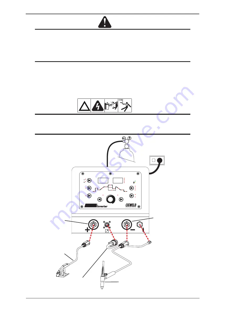
D. Connect the TIG torch trigger switch via the 8 pin socket located on the front of the power source as shown
below. The TIG torch will require a trigger switch to operate in Lift TIG or HF TIG Mode.
NOTE
If the TIG torch has a remote TIG torch current control fitted then it will require to be connected to
the 8 pin socket. (Refer to section 3.08.2 Remote Control Socket for further information).
E. Fit the welding grade shielding gas regulator/flowmeter to the shielding gas cylinder (refer to Section
3.12) then connect the shielding gas hose from the regulator/flowmeter outlet gas INLET on the rear of
the WeldSkill 200 AC/DC Power Source. Connect the gas hose from the TIG torch to the gas OUTLET on
on the front of the WeldSkill 200 AC/DC Power Source.
!
WARNING
Before connecting the work clamp to the work make sure the mains power supply is switched off.
Secure the welding grade shielding gas cylinder in an upright position by chaining it to a suitable
stationary support to prevent falling or tipping.
FAULT
POWER
Amps
Volts
FORWARD
BACK
VOLTS
SECONDS
PERCENT (%)
FREQ (Hz)
AC FREQUENCY
WAVE BALANCE
(ARC FORCE)
MODE
AC
DC
PULSE
PURGE
PROCESS
TRIGGER
2T NORMAL
4T LATCH
HF TIG
LIFT TIG
STICK
Pre
Flow
Hot
Start
Initial
Current
Up
Slope
Base
Current
Peak
Current
Width
Trough
Current
Frequency
Down
Slope
Crater
Current
Post
Flow
WeldSkill
PORTABLE WELDING MACHINE
200
AC/DC
Inverter
2 0 0
1 8 . 0
8
Negative Welding
Terminal (-)
Work Lead
Positive Welding
Terminal (+)
8 Pin Control Socket
Tig Torch
A-11224
Figure 3-9: Setup for TIG Welding