background image

PART I: SPECIFICATIONS

7


(*) NOTE ON THE BURNER WORKING SERVICE: 

LMV2x automatically stops after 24h of continuous working. The device immedia-

telystarts up, automatically. LMV3x performs countinuous operation.
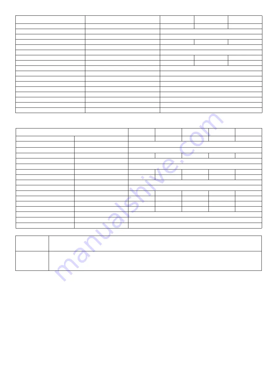
BURNER TYPE

R91A L-..

R92A L-..

R93A L-..

Output

min. - max. kW

480 - 2670

480 - 3050

550 - 4100

Fuel

L -  

LPG

Category

I

3B/P

Gas rate- 

LPG

min.- max. (Stm

3

/h)

17.9 - 100

17.9 - 114

20 - 153

Gas pressure

mbar

(

see Note 2

)

Power supply

230V 3~ / 400V 3N ~ 50Hz

Total power consumption

kW

4.5

6.0

8.0

Electric motor

kW

4

5.5

7.5

Protection

IP40

Operation

Progressive - Fully modulating

Gas train 50

Valves size / Gas connection

50 / Rp 2

Gas train 65

Valves size / Gas connection

65 / DN65

Gas train 80

Valves size / Gas connection

80 / DN80

Gas train 100

Valves size / Gas connection

100 / DN100

Operating temperature

°C

-10 ÷ +50

Storage Temperature

°C

-20 ÷ +60

Working service (*)

Intermitent

BURNER TYPE

R512A M-..

R515A M-..

R520A M-..

R525A M-...50 R525A M-...xx

Output

min. - max. kW

600 - 4500

770 - 5200

1000 - 6400

2000 - 6700

2000 - 8000

Fuel

M - 

Natural gas

Category

(

see next paragraph

)

Gas rate- 

Natural gas

min.- max. (Stm

3

/h)

63 - 476

81 - 550

106 - 677

212 - 709

212 - 847

PressureGas pressure

mbar

(

see Note 2

)

Power supply

230V 3~ / 400V 3N ~ 50Hz

Total power consumption

kW

9.7

11.5

16.5

19

19

Electric motor

kW

9.2

11

15

18.5

18.5

Protection

IP40

Operation

Progressive - Fully modulating

Gas train 50

Valves size / Gas connection

50 / Rp2

50 / Rp2

50 / Rp2

50 / Rp2

Gas train 65

Valves size / Gas connection

65 / DN65

65 / DN65

65 / DN65

-

65 / DN65

Gas train 80

Valves size / Gas connection

80 / DN80

80 / DN80

80 / DN80

-

80 / DN80

Gas train 100

Valves size / Gas connection

100 / DN100

100 / DN100

100 / DN100

-

100 / DN100

Operating temperature

°C

-10 ÷ +50

Storage Temperature

°C

-20 ÷ +60

Working service (*)

Intermitent

Note1: 

All gas flow rates are referred to Stm

3

/h (1013 mbar  absolute pressure, 15 °C temperature) and are valid for G20 gas 

(net calorific value H

= 34.02 MJ/Stm

3

); for L.P.G. (net calorific value H

= 93.5 MJ/Stm

3

)

Note2:

Maximum gas pressure =  360mbar (with


Dungs MBDLE)

                                              =  500mbar (with


Siemens VGD)

Minimum gas pressure = see gas curves.

Summary of Contents for R512A L Series

Page 1: ...M039240CC 2 5 03 2015 BURNERS BRUCIATORI BRULERS BRENNER QUEMADORES LMV2x 3x Microprocessor controlled gas burners MANUAL OF INSTALLATION USE MAINTENANCE R91A R92A R93A R512A R515A R520A R525A...

Page 2: ...CTIONS FOR BURNERS z The burner should be installed in a suitable room with ventilation openings complying with the requirements of the regulations in force and sufficient for good combustion z Only b...

Page 3: ...ditions such as the development of toxic or explosive mixtures DIRECTIVES AND STANDARDS Gas burners European directives Directive 2009 142 EC Gas Appliances Directive 2006 95 EC on low voltage Directi...

Page 4: ...apparatus EN 50165 Electrical equipment of non electric appliances for household and similar purposes Safety requirements UNI EN 746 2 Industrial thermoprocessing equipment Burner data plate For the...

Page 5: ...one for ces the pressure in the utilisation limits The actuators move proportionally the air damper and the gas butterfly valve in order to achieve the optimisation of the gas flue values as to get a...

Page 6: ...micro processor control without inverter EB micro processor control with inverter BURNER TYPE R91A M R92A M R93A M Output min max kW 480 2670 480 3050 550 4100 Fuel M Natural gas Category see next pa...

Page 7: ...t min max kW 600 4500 770 5200 1000 6400 2000 6700 2000 8000 Fuel M Natural gas Category see next paragraph Gas rate Natural gas min max Stm3 h 63 476 81 550 106 677 212 709 212 847 PressureGas pressu...

Page 8: ...in 65 Valves size Gas connection 65 DN65 65 DN65 65 DN65 65 DN65 Gas train 80 Valves size Gas connection 80 DN80 80 DN80 80 DN80 80 DN80 Gas train 100 Valves size Gas connection 100 DN100 100 DN100 10...

Page 9: ...441 866 421 1406 971 435 269 299 228 447 360 464 M12 424 280 310 300 632 148 484 846 292 649 228 185 R92A 80 1356 242 35 579 132 490 441 866 421 1437 1002 435 269 299 228 447 360 464 M12 424 280 310 3...

Page 10: ...145 530 517 969 446 1726 1082 644 380 420 494 540 494 M14 552 390 390 791 149 642 942 353 764 316 270 R520A 50 1499 320 35 595 100 530 517 969 446 1590 946 644 400 440 494 540 604 M14 552 390 390 763...

Page 11: ...o the available gas pressure value upstream the burner s gas valve Then subtract the backpressure The result is called pgas Draw a vertical line matching the furnace input value 600kW in the example q...

Page 12: ...is set in order to find a compromise between the burner output and the generator specifications that is why the minimum output may be different from the Per formance curve minimum BACK PRESSURE IN COM...

Page 13: ...R520A M Stm3 h GAS PRESSURE mbar R525A M Rp2 Stm3 h R525A M DN65 80 100 Stm3 h Caution the gas rate value is quoted on the x axis the related network pressure is quoted on the y axis pressure value in...

Page 14: ...3 h GAS PRESSURE mbar R520A L Stm3 h Caution the gas rate value is quoted on the x axis the related network pressure is quoted on the y axis pressure value in the combustion chamber is not included To...

Page 15: ...the combustion chamber 3 Gas pressure outlet on the butterfly valve 4 Differential pressure gauge 2 10 Measuring the gas pressure in the combustion head In order to measure the pressure in the combust...

Page 16: ...0 100 120 140 160 180 200 220 240 260 280 300 0 5 10 15 20 25 30 35 40 45 40 60 80 100 120 140 160 180 200 220 240 260 280 300 320 340 0 5 10 15 20 25 30 35 40 45 50 50 75 100 125 150 175 200 225 250...

Page 17: ...Stm3 h R93A L Stm3 h Gas pressure in combustion head R512A L Stm3 h GAS PRESSURE mbar R520A L Stm3 h 0 2 4 6 8 10 12 14 16 18 20 22 24 26 10 20 30 40 50 60 70 80 90 100 110 0 10 20 30 40 50 60 70 10...

Page 18: ...llowing are placed in each packing case z burner with detached gas train z gasket or ceramic fibre plait according to burner type to be inserted between the burner and the boiler z envelope containing...

Page 19: ...In case the burner must be coupled with boilers with a combustion chamber smaller in dia meter or shorter than those described in the diagram please contact the supplier to verify that a correct match...

Page 20: ...tes the utilisation please contact the manifacturer Fig 3 Key a Heat output in kW b Lenght of the flame tube in meters c Flame tube firing intensity in MW m3 d Combustion chamber diameter m Fig 3 Firi...

Page 21: ...ets are not part of the standard supply ATTENTION BEFORE EXECUTING THE CONNECTIONS TO THE GAS PIPE NETWORK BE SURE THAT THE MANUAL CUTOFF VALVES ARE CLOSED Gas train with valves group VGD with built i...

Page 22: ...tted z Connect the reference gas pipe TP in figure 8mm external size pipe supplied loose to the gas pressure nipples placed on the gas pipe downstream the gas valves gas pressure must be measured at a...

Page 23: ...pressure Test atmospheric pressure EV1 closes and keep this position for a preset time test time td1 The pressure switch PGCP has not to detect a rise of pressure z Test space filling EV2 opens and k...

Page 24: ...terminal X3 04 4 in case of LMV2x LMV3x LMV5x LME7x on the board and the earth terminal an RC Siemens RC466890660 filter must be inserted For LMV5 control box please refer to the clabeling recommendat...

Page 25: ...VER OPEN OR DISMANTLE ANY COMPONENT OF THE MACHINE EXCEPT FOR ITS MAINTENANCE TO SECURE THE MACHINE ACT ON THE ISOLATOR SWITCH IN CASE OF ANOMALIES THAT REQUIRED A SHUT DOWN OF THE BURNER IT S POSSIBL...

Page 26: ...the gas pressure is sufficient signalled by an error code on the AZL display z At the beginning of the start up cycle the actuator drives the air damper to the maximum opening position then the fan m...

Page 27: ...me output increasing too much or that the flues temperature gets too low to cause condensation in the chimney 7 2 User interface The AZL2x display is shown below The keys functions are the following W...

Page 28: ...Serivce during the curve adjustments Key Used to increase a a value Used to enter Info and Serivce during the curve adjustments Keys ESC By pressing and at the same time the ESCAPE function is perfome...

Page 29: ...asformatore accen sione ON TSA1 1st safety time ignition transformer ON Ph42 TSA1 primo tempo sicurezza trasformatore accen sione OFF TSA1 1st safety time ignition transformer OFF t42 preignition time...

Page 30: ...splay will show InFo Press the enter InFo key 3 then il will show the first code 167 flashing on the right side it will show the data entered By pressing or it is possible to scroll up or down the par...

Page 31: ...or by pressing ESC or InFo for more seconds the display will show 9 Once the last parameter is accessed 143 by pressing the End message will flash 10 Press InFo for more than three seconds or for mor...

Page 32: ...the reset press InFo for one second The unit displays an event which does not lead to shutdown The display shows current error code c alternating with diagnostic code d Press InFo to return to the dis...

Page 33: ...ner control panel see next picture instead of the TAB thermo stat as described on the previous paragraphs about the progressive burners Go on adjusting the burner as described before paying attention...

Page 34: ...Slowly fully open the manual cutoff valve z Refit the transparent plastic cover on the pressure switch 7 7 Adjusting the maximum gas pressure switch when provided To calibrate the maximum pressure sw...

Page 35: ...n head towards the MIN position by turning clockwise the VRT ring nut Fasten VB screw when the adjustment is accomplished 7 11 Center head holes gas flow regulation natural gas burners To adjust the g...

Page 36: ...on the adjusting plate notches and let it move CW CCW as to open close the holes 3 once the adjustmet is performed fasten the V screws The adjusting plate correct position must be regulated in the pla...

Page 37: ...ollows 1 remove the cap unscrewing the fixing screws A 2 remove the filtering cartridge B clean it using water and soap blow it with compressed air or replace it if necessary 3 replace the cartridge i...

Page 38: ...e described above having care to place correctly the O ring OR between burner and gas manifold To replace the spring in the gas valve group proceed as follows 1 Carefully twist the protection cap 1 an...

Page 39: ...ack to the outside and remove the combustion head D 6 loose the screw of th eignition electrodes support E 7 remove the electrodes and replace them paying attention to the measures showed in figure F...

Page 40: ...etector 8 8 Checking the detection current L P G To check the detection signal follow the scheme in the picture below If the signal is less than the value indicated check the position of the detection...

Page 41: ...proceed as follows 1 turn the burner main switch to 0 Off position 2 disconnect the power mains 3 close the fuel valve of the supply line 8 10 Burner disposal In case of disposal follow the instructio...

Page 42: ...MAINTENANCE 42 9 0 WIRING DIAGRAMS Refer to the attached wiring diagrams WARNING 1 Electrical supply 230V 50Hz 1 a c 400V 50Hz 3N a c 2 Do not reverse phase with neutral 3 Ensure burner is properly e...

Page 43: ...AS z z MAXIMUM GAS PRESSURE SWITCH DEFECTIVE z z THERMOSTATS PRESSURE SWITCHES DEFECTIVES z z z OVERLOAD TRIPPED INTERVENTION z AUXILIARIES FUSE INTERRUPTED z DEFECTIVE CONTROL BOX z z z z z DEFECTIVE...

Page 44: ...B A C B 11 2 11 3 1 2 6 7 2 6 13 6 5 9 2 9 3 3 4 1 1 4 1 2 7 3 1 7 4 6 1 6 1 1 6 2 10 2 5 11 6 1 8 1 6 7 1 9 1 4 1 3 12 2 11 5 6 3 14 2 5 14 2 4 15 13 1 13 2 8 2 6 4 7 3 4 7 1 7 2 12 1 14 1 14 2 3 11...

Page 45: ...2 5 CONTROL PANEL 4 2 BUTTERFLY GAS VALVE 9 2 COUPLING 15 BRACKET 5 IGNITION CABLE 9 3 BRACKET 16 DETECTION CABLE 6 1 BURNER HOUSING 10 1 FAN WHEEL 6 1 1 COVER 10 2 MOTOR 6 2 INSPECTION GLASS 11 1 DE...

Page 46: ......

Page 47: ......

Page 48: ...ia L Galvani 9 35011 Campodarsego PD ITALY Tel 39 049 9200944 Fax 39 049 9200945 9201269 web site www cibunigas it e mail cibunigas cibunigas it Note specifications and data subject to change Errors a...

Reviews: