20MACIE0440
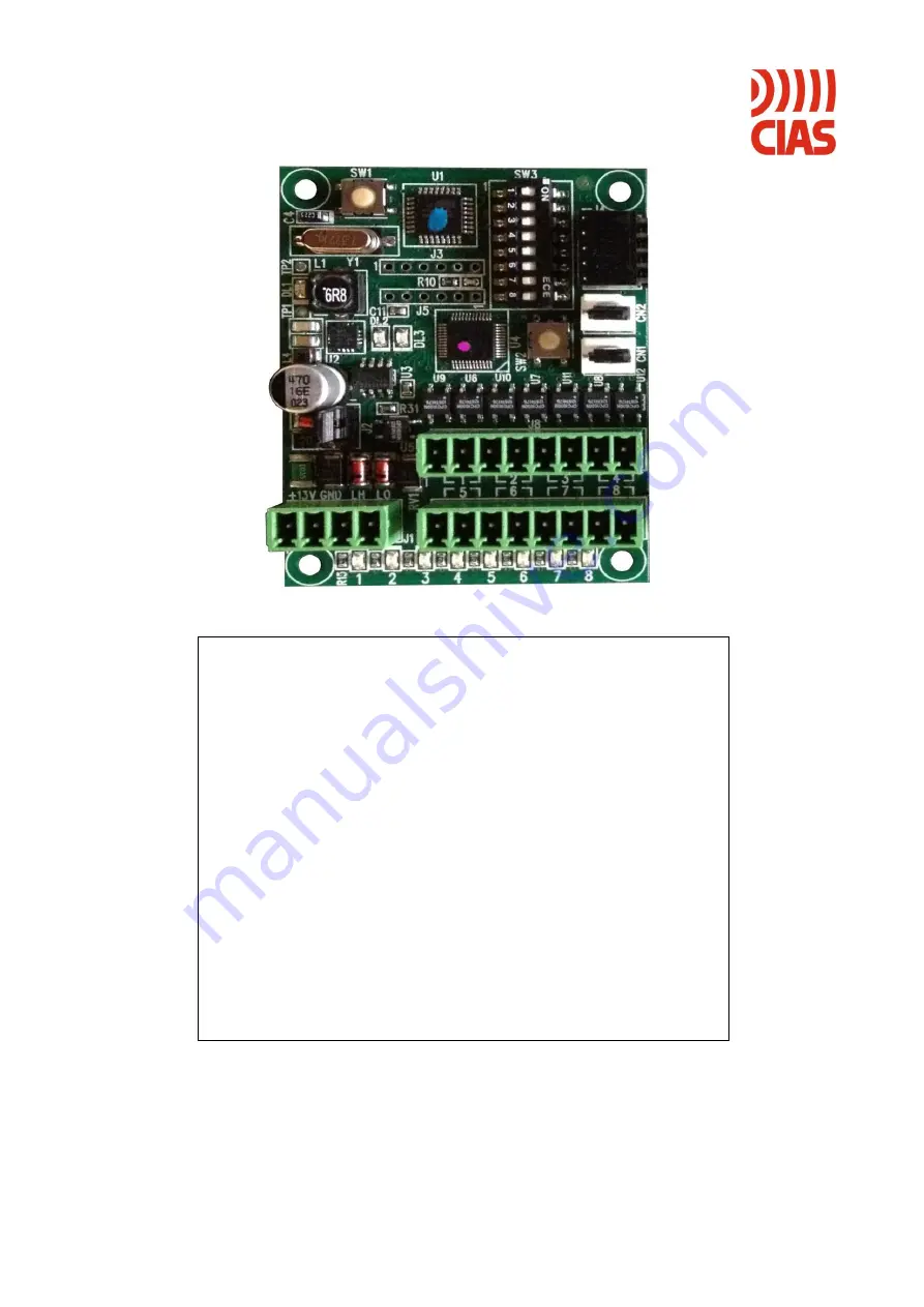
MICRO-RAY-CARD8
Modulo concentratore per barriere
Micro-Ray
Manuale di Installazione
Alarm collector module for
Micro-Ray barriers
Installation Manual
Edizione / Edition 1.1
Page 1: ...20MACIE0440 MICRO RAY CARD8 Modulo concentratore per barriere Micro Ray Manuale di Installazione Alarm collector module for Micro Ray barriers Installation Manual Edizione Edition 1 1...
Page 2: ...in modalit Multipla 5 2 4 2 MODO 2 Master in modalit Multipla e Slave in modalit Singola 5 3 TIPOLOGIE DI COLLEGAMENTO 6 3 1 Collegamento Seriale 6 3 2 Collegamento Ethernet 6 4 MORSETTIERE CONNETTOR...
Page 3: ...1 MODE 1 Master and Slave in Multiple mode 14 2 4 2 MODE 2 Master in Multiple mode and Slave in Single mode 14 3 CONNECTIONS MODE 15 3 1 Serial RS485 15 3 2 Ethernet connection 15 4 TERMINAL BLOCKS CO...
Page 4: ...redisposto come barriera singola oppure i medesimi stati provenienti da pi barriere perdendo la definizione dei raggi se predisposto come barriera multipla Il dispositivo viene connesso all alimentazi...
Page 5: ...essere indirizzate di conseguenza considerando che ogni Micro Ray Card8 in questa configurazione in grado di gestire due barriere 2 4 2 MODO 2 Master in modalit Multipla e Slave in modalit Singola In...
Page 6: ...e riportate nei precedenti paragrafi 3 2 Collegamento Ethernet Questa configurazione consente di sfruttare la rete Ethernet per trasmettere le informazioni provenienti da una o pi barriere Micro Ray m...
Page 7: ...CARD8 SLAVE QUASAR IPDOORWAY IP Address con Gateway e Network Mask Port Number deve essere lo stesso per tutti gli IP DOORWAY appartenenti allo stesso gruppo che collegano al massimo sei barriere dive...
Page 8: ...Impostazione Barriera Multipla OUT1 1a 1b Allarme generale Allarme barriera n OUT2 2a 2b Guasto no answer generale Guasto no answer barriera n OUT3 3a 3b Manomissione colonna A Manomissione colonna A...
Page 9: ...na B barriera n 1 Tabella 4 Led di segnalazione presenti sulla scheda Micro Ray Card8 TAMPER CN1 Segnalazione apertura contenitore Pin FUNZIONE 1 GND 2 Ingresso Tamper 3 GND Tabella 5 Tamper CN1 prese...
Page 10: ...8 Per associare l indirizzo della scheda Micro Ray Card8 al n di tratta della barriera da gestire utilizzare i dip switch da S3 a S6 seguendo quanto indicato nella tabella 11 N TRATTA BARRIERA SW3 S6...
Page 11: ...i dalla barriera Micro Ray RELE di ALLARME 1 Allarme Intrusione su Ricevitore 2 Allarme mascheramento su Ricevitore 3 Segnale ricevuto insufficiente V RAG 6 99V 4 Allarme canale RELE di MANOMISSIONE C...
Page 12: ...icroprocessore Errore nella connessione della linea seriale RS 485 Controllare le connessioni della linea seriale RS 485 Tabella 13 Ricerca guasti 6 CARATTERISTICHE TECNICHE 6 1 Tabella caratteristich...
Page 13: ...er and Fault No answer states if set as single barrier or the same states coming from some barriers losing the definition of the rays if set as multiple barrier The device is connected to the power su...
Page 14: ...r Slave device will need to be addressed accordingly considering that each Micro Ray Card8 in this configuration can manage two barriers 2 4 2 MODE 2 Master in Multiple mode and Slave in Single mode I...
Page 15: ...he previous paragraphs 3 2 Ethernet connection This configuration allows you to use the Ethernet network to transmit information from one or more Micro Ray barriers maximum 6 per group to micro ray ca...
Page 16: ...SERIALE RS 485 CARD8 MASTER CARD8 SLAVE CARD8 SLAVE QUASAR IPDOORWAY Apply IP DOORWAYs in Micro Ray columns as shown in their user manual Connect micro ray card8 serials line J1 to the QUASAR IPDOORWA...
Page 17: ...outputs Term Set as Single Barrier Set as Multiple Barriera OUT1 1a 1b General Alarm Alarm barrier n OUT2 2a 2b General fault no answer Alarm barrier n OUT3 3a 3b Column A tamper Tamper column A barr...
Page 18: ...ed on ray 1 indication Column B tamper barriera n 1 Table 4 Leds on the Micro Ray Card8 board TAMPER CN1 Cover opening signaling Pin FUNCTION 1 GND 2 Tamper Input 3 GND Table 5 Tamper CN1 on the Micro...
Page 19: ...Micro Ray Card8 address to the barrier number to be managed use dip switches S3 to S6 as shown in table 11 BARRIER NUMBER SW3 S6 SW3 S5 SW3 S4 SW3 S3 1 OFF OFF OFF OFF 2 OFF OFF OFF ON 3 OFF OFF ON OF...
Page 20: ...ollowing events generated by the Micro Ray barrier ALARM RELAY 1 Intrusion alarm on Receiver 2 Masking alarm on Receiver 3 Insufficient signal received V RAG 6 99V 4 Channel alarm TAMPER RELAY COLUMNS...
Page 21: ...o reset the microprocessor RS 485 serial line connection error Check the RS 485 serial line connections Table 17 Troubleshooting 6 TECHNICAL SPECIFICATIONS 6 1 Technical specifications table single Ma...
Page 22: ...CIAS Elettronica S r l Ed 1 1 Installation Manual Page 22 of 23 Micro Ray Card8 NOTE...
Page 23: ...CIAS Elettronica S r l Ed 1 1 Installation Manual Page 23 of 23 Micro Ray Card8 NOTE...
Page 24: ...elettroniche minimizzare l uso delle discariche per lo smaltimento dei prodotti e migliorare la qualit della vita evitando che sostanze potenzialmente pericolose vengano rilasciate nell ambiente This...