background image

CIARA

 Horizon D10500 / T10500


- 7 - 

1.2 Choosing a site for the system 

All CIARA computers operate reliably in a typical office or home environment.  Choose a location that is readily accessible and meets 
the following requirements : 


Is near a grounded, three-pronged power outlet 


The socket-outlet shall be installed near the equipment and shall be easily accessible. 


Is clean and dust free. 


Is well-ventilated and lighted and away from sources of heat. 


Is isolated from strong electromagnetic fields produced by electrical devices. 

(I.e. air conditioners, large fans, large electric motors, radio and TV transmitters) 


Has an appropriate table or desk that will allow you to work without physical discomfort and strain. 

 
The power supply input should be 120 V, 10 A and 60 Hz.  


A few general precautions should always be observed : 


Never connect any peripheral such as a monitor to the system unit if the power is turned "ON".  Always shut down the system 
first. 


Never remove any internal adapter cards in the system unit if the power is turned "ON" as this will ruin the Card/Computer 
and Void the Warranty. 


Never install and connect more peripherals than available power supply plugs to avoid exceeding the maximum power of the 
system.  


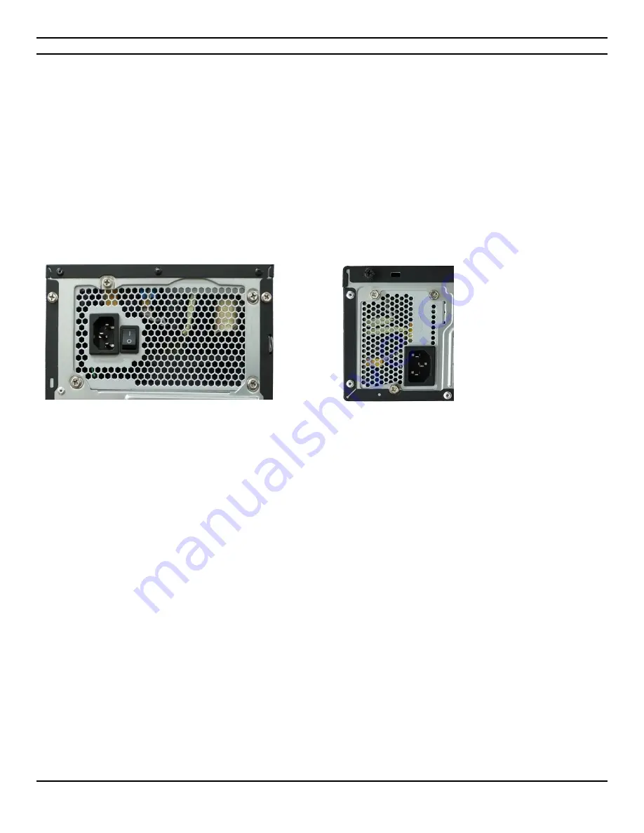
NOTE   The Horizon D10500 and T10500 models come either with or without a power supply On/OFF switch. For those systems that do 
not have a switch, make sure to shut down the system through Windows before proceeding to any repair or replacement work inside 
the system.


Summary of Contents for Horizon D10500

Page 1: ...User Guide Horizon D10500 T10500 ...

Page 2: ...Server 2016 are registered trademarks of Microsoft Corporation AMD and Rizen are trademarks or registered trademarks of Advanced Micro Devices Inc Asus is a trademark of ASUSTeK COMPUTER INC All other names brands and trademarks are trademarks of their respective companies Fourth printing September 2021 Printed in Canada All rights reserved Hypertechnologie CIARA inc ...

Page 3: ...optical drive problems 23 1 6 Component installation guide 24 1 6 1 Precautions against static electricity 24 1 6 2 Opening and accessing the chassis 25 1 6 3 Insertion of the processor 27 Apply the Thermal Interface Material to the CPU heatsink and CPU before you install the heatsink and fan if necessary 27 1 6 4 Installation of the memory modules 28 1 6 5 Installation of the optical drive module...

Page 4: ...yboard 60 4 8 Graphics subsystem 61 4 8 1 Integrated graphics 61 4 8 2 DisplayPort 1 2 61 Maximum resolution 4096 x 2304 60 Hz 61 4 8 3 HDMI 2 1 port 61 4 9 Audio subsystem 62 4 10 I O Port set up 62 4 11 LAN subsystem 63 4 11 1 Realtek RTL8111H Gigabit Ethernet controller 63 4 11 2 RJ 45 LAN connectors LEDs 63 4 12 Trusted Platform Module TPM 64 4 13 Replacing the system battery 64 4 14 Installin...

Page 5: ...e shooting certification detailed description and a Glossary Please remember to fill out the Equipment Log and keep a copy in a safe place With proper care and operating procedures your CIARA Horizon D10500 T10500 will give you many years of service and high performance computing NOTE This User s guide uses Horizon D10500 T10500 designation where T10500 refers to the tower model and D10500 refers ...

Page 6: ...during transit The keyboard is on the top of the box the other accessories are completely underneath Carefully unpack your computer and be sure to save all boxboards for future shipping and transportation To repack the PC it may be easier to place the moulded cushioning on the ends of the PC and then slide the box over the PC together with the cushioning rather than lifting the PC ...

Page 7: ... that will allow you to work without physical discomfort and strain The power supply input should be 120 V 10 A and 60 Hz A few general precautions should always be observed Never connect any peripheral such as a monitor to the system unit if the power is turned ON Always shut down the system first Never remove any internal adapter cards in the system unit if the power is turned ON as this will ru...

Page 8: ...rizon D10500 T10500 8 1 3 Peripheric installation USB 3 2 gen 2 devices HDMI port Mouse Keyboard USB 2 0 devices USB 3 2 gen 1 devices Microphone Audio out Audio in Network RJ 45 USB gen 2 devices DisplayPorts ...

Page 9: ... then start 2 Accept the EULA and press on Continue 3 Select 32 bit or 64 bit and press Start System Recovery 4 A pop up will then open warning you that all the data will be lost If all your files are already saved press OK 5 The recovery will take around 30 minutes to complete A window will show you the process of the recovery once completed Eject the DVD then press OK The system will then reboot...

Page 10: ...t to the Windows Startup Settings screen in Windows 10 If you re not signed in to Windows tap or click the power icon from the sign in screen hold Shift and then tap or click Restart Or if you re already signed in 1 Click on windows button select Settings and then select Update security 2 From left select Recovery 3 Under Advanced startup tap or click Restart now 4 On the Choose an option screen t...

Page 11: ...CIARA Horizon D10500 T10500 11 Choose Reset your PC Choose Remove everything Press next Then follow the regular Windows 10 Installation process ...

Page 12: ...cover BIOS settings To ensure system compatibility and stability we recommend that you press F5 to load default BIOS values DO NOT shut down or reset the system while updating the BIOS Doing so can cause system boot failure 1 3 4 System maintenance Read and follow carefully all the instructions and warnings in this manual and on these products Only use a damp cloth to clean your system unit and mo...

Page 13: ... provides a screen composed of icons You select or click on the icons to run programs As noted above Windows has been installed on your computer For further information about using Windows please consult the appropriate Microsoft software manual provided with your CIARA Horizon D10500 T10500 1 3 5 4 Windows Server 2019 2016 and Linux Windows Server 2019 Windows Server 2016 and Linux are operating ...

Page 14: ... power button for at least four seconds then press the power button again to restart the computer If the system will not shut down unplug the power cord wait a few seconds and then plug it in again The computer will restart if automatic start on power loss is set in the BIOS If it does not restart press the power button to start the computer Be sure that all the needed device drivers have been ins...

Page 15: ...han four seconds Otherwise the computer will shut down and you will lose your data Computer date and time display is incorrect RTC real time clock battery may need to be replaced Connecting the computer to a live AC outlet prolongs the life of the RTC battery Reset the date and time under Control Panel Computer Setup can also be used to update the RTC date and time If the problem persists replace ...

Page 16: ...2 Open the hood See article 1 6 2 and ensure the 4 wire power supply cable is seated into the connector on the system board Check if a device is causing the problem by removing ALL attached devices such as hard or optical drives and expansion cards Power on the system If the system enters the POST then power off and replace one device at a time and repeat this procedure until failure occurs Replac...

Page 17: ...rt click Explore and select a drive Select File Properties Tools Under Error checking click Check Now Drive not found Cable could be loose Check cable connections System files missing or not properly installed For Windows 7 the system will need to be booted with a system DVD and the repair option selected to try and fix problems Computer seems to be locked up Program in use has stopped responding ...

Page 18: ... graphics card 1 Reseat the graphics card Power on the system 2 If the problem persists contact CIARA since the problem may necessitate the replacement of the graphics card or the motherboard Dim characters The brightness and contrast controls are not set properly Adjust the monitor brightness and contrast controls Cables are not properly connected Check that the graphics cable is securely connect...

Page 19: ...udio The hard disk may be full Before recording make sure there is enough free space on the hard disk You can also try recording the audio file in a compressed format 1 5 5 Solving printer problems Printer will not print Printer is not turned on and online Turn the printer on and make sure it is online The correct printer drivers for the application are not installed Install the correct printer dr...

Page 20: ...r seconds Otherwise the computer will shut down and you will lose your data Cursor will not move using the arrow keys on the keypad The Num Lock key may be on Press the Num Lock key The Num Lock light should not be on if you want to use the arrow keys Mouse does not respond to movement or is too slow Mouse connector is not properly plugged into the back of the computer Connect mouse properly Mouse...

Page 21: ...ng memory modules were used in the upgrade or memory modules were installed in the wrong location See Sections 1 6 4 and 4 23 of the present Guide to verify if you have installed memory modules compatible to your system and if they were installed correctly If the problem persists Contact CIARA Power LED flashes five times once every second followed by a two second pause and the computer beeps five...

Page 22: ...for the replacement of the module 4 4 If the problem persists Contact CIARA for this may necessitate the replacement of the motherboard 1 5 9 Solving processor problems Solving processor problems Problem Cause Solution Poor performance is experienced Processor is hot 1 Make sure the airflow to the computer is not blocked 2 Make sure the fans are connected and working properly some fans only operat...

Page 23: ...not properly seated in the drive Turn off the computer and insert a thin metal rod into the emergency eject hole and push firmly Slowly pull the tray out from the drive until the tray is fully extended then remove the disc The optical drive cannot read a disc or takes too long to start CD or DVD has been inserted upside down Re insert the CD or DVD with the label facing up The DVD drive takes long...

Page 24: ... shocks arising from static electricity It is hence important to wear antistatic smock gloves shoes and ankle during the installation process Here are a few examples of protective equipment Typical antistatic foot ground device Antistatic shoes with foot ground device Note that the floor surface is also antistatic Antistatic smock and gloves Note that the table surface is also antistatic ...

Page 25: ...sis 1 6 2 1 Opening and accessing the Horizon T10500 chassis To remove the side panel simply press the release button and slide the panel back and then remove it The side panel is then removed from the chassis allowing for modular installation and chassis preparations ...

Page 26: ...ning and accessing the Horizon D10500 chassis To remove the cover simply press the release button and slide the panel back and then remove it The cover is then removed from the chassis allowing for modular installation and chassis preparations ...

Page 27: ...ower cables before installing the CPU The AM4 socket has a different pinout design Ensure that you use a CPU designed for the AM4 socket The CPU fits in only one correct orientation DO NOT force the CPU into the socket to prevent bending the connectors on the socket and damaging the CPU Apply the Thermal Interface Material to the CPU heatsink and CPU before you install the heatsink and fan if nece...

Page 28: ...el configuration install a matched pair of DIMMs equal in speed and size in DIMM A1 and DIMM B1 of channel 1 Then install another DIMM equal to the speed and total size of the DIMMs installed in channel A in either DIMM 2 or DIMM 4 of channel B If you ignore this recommendation the system will operate in single channel mode without taking advantage of the dual channel technology You may install 8 ...

Page 29: ...incorrectly Slide the module into the socket at a 90 degree angle to the main board See figure below After inserting the DIMM module completely into the socket push up on the socket latches securing the DIMM into place NOTE To release the memory module push both latches down and carefully rock the module away from the main board You should then be able to pull the module up and out of the socket A...

Page 30: ... module so that the pin 1 marking on the module corresponds to the DIMM socket pin 1 marking The module can only fit in the socket in one way you cannot insert the DIMM incorrectly 3 After inserting the DIMM module completely into the socket push up on the socket latches securing the DIMM into place 4 To remove a DIMM release the locking tab and pull out the DIMM ...

Page 31: ...e optical drive module Horizon T10500 The optical drive is removed or inserted into the front end of the chassis To remove the drive lift the locking tab To secure the drive clip down the locking tab Connect the power and SATA cables to the drive SATA cable must be connected to one of the four SATA ports ...

Page 32: ...the optical drive module Horizon D10500 Push the latch and lift the bays that can accommodate the drives and the optical drive Install the slide on the right side of the optical drive Slide the optical drive face down into its bay until it clicks into place ...

Page 33: ...CIARA Horizon D10500 T10500 33 Connect the power cable and the SATA cable Lower the array ...

Page 34: ... inside of the casing To remove the hard drive pull the locking tab To secure the drive push down the locking tabs Then connect the power cable and the SATA cable The SATA SSD is installed with screws at the bottom of the drive cage Connect the SSD to the power supply Then connect one end of a SATA data cable to the SSD Connect the other ends of the SATA data cable to one of the SATA ports ...

Page 35: ...SATA hard drive and SSD Horizon D10500 Push the latch and lift the bays that can accommodate the drives and the optical drive The hard disk or SSD is inserted without tools into its plastic disk holder Slightly spread the sides to insert pins in the drive holes ...

Page 36: ... T10500 36 Slide the tool less disk holder in the 2 5 bay for the SSD or 3 5 bay fir the hard drive To release the disc squeeze the latch and pull the handle Connect the drive to the power supply and to the SATA controller ...

Page 37: ...allation of the M 2 SSD drive Horizon D10500 and T10500 Locate the M 2 slots to insert the M 2 SSD The M 2 SSD is inserted with an angle in the slot and then lowered down Fasten the M 2 SSD with the included screw The M 2 SSD is now ready to use ...

Page 38: ... Drive Bay Space Ext 2 x 5 25 Ext 1 x 3 5 Int 2 x 3 5 Power Source 350 W 80 PLUS Bronze Peripheral Space 1 PCI Express x4 slot 1 conventional PCI slot and 1 video PCI Express x16 slot Dimensions 363 mm H x 180 mm W x 390 mm D Casing fan 1 x 92 mm Security Kensington slot and padlock loop Sheet Metal Thickness 0 5 mm Front Rear Open side Intrusion switch Padlock loop Kensington slot ...

Page 39: ... x 3 5 and 1 x 2 5 Power supply TFX 300 W 80 PLUS Bronze Peripheral space 1 PCI Express x4 slot 1 conventional PCI slot and 1 video PCI Express x16 slot Dimensions mm without front bezel 102 mm H x 338 mm W x 356 mm D 12 27 liter Casing fan 1 x 80 mm Security Kensington slot and safety loop Metal thickness 0 6 mm Front Rear Internal Security Intrusion switch Cover latch Kensington slot Safety loop...

Page 40: ... All CIARA Horizon D10500 T10500 series computers are certified by Intertek Canada and United States and meet or exceed the Class B limitations for Radio noise emissions from digital apparatus as set out in the Radio Interference Regulations of Industry Canada 2 1 Radio interference precautions To minimize the likelihood of interference being caused to any radio or TV equipment CIARA recommends th...

Page 41: ... Importer CIARA 9300 Trans Canada Highway Montreal Quebec H4S 1K5 Tel 514 798 8880 Fax 514 798 8889 Declare that the product Personal Computer System CIARA Horizon D10500 T10500 is in conformity with ICES 003 and Part 15 subpart B of the FCC Rules Robert Ahdoot President CIARA ...

Page 42: ...nd on the user is encouraged to try to correct the interference by one or more of the following measures Reorient or relocate the receiving antenna Increase the distance between the equipment and the receiver Connect the equipment into an outlet on a circuit different from that to which the receiver is connected Consult the vendor or an experienced radio TV technician for help Warning Changes or m...

Page 43: ...n addition to increased energy efficiency If the CIARA Horizon D10500 T10500 computers cost more than a conventional less efficient computer purchasers will recover their investment in increased energy efficiency through utility bill savings within a reasonable period of time Energy efficiency can be achieved through broadly available non proprietary technologies offered by more than one manufactu...

Page 44: ...ree year warranty additional to the standard one year warranty If you are interested in purchasing a warranty extension please contact your CIARA representative within one month of receipt of your system If you have purchased a different type of warranty or an extension to the standard warranty you will need to provide the CIARA Service Contract Number to the Customer Support representative when p...

Page 45: ...c commands change or verify parameter settings etc The service support personnel may be able to rectify the problem over the telephone at which time you should ask for and record the unique call number for your own records If the support group is unable to resolve the problem remotely an On Site call may be generated or additional information will be provided to you to obtain a Returned Merchandis...

Page 46: ... a period of ninety 90 days from the date of purchase by the end user In the event of defective media as your exclusive remedy and the sole liability of CIARA CIARA will replace the defective media at no charge to you if you return the defective media with prepaid shipping to CIARA within the warranty period Except for this media warranty this software is provided As is and CIARA disclaims any and...

Page 47: ...he system components dates of component removal and or replacement Be sure to include the same information for any components added to the system such as fixed disk add in boards or printers Record the model and serial numbers of the CIARA System The model and serial numbers of the System Unit are recorded on the label attached to the rear cover The location of serial numbers on add in boards fixe...

Page 48: ...s Pro B550M C CSM HelpDesk_CPU All versions utilize essentially the same Set Up and configuration procedures and the same Asus BIOS Other processors may be supported in the future This board is designed to support processors with a maximum wattage of 125 W The processors listed are only supported when falling within the wattage requirements of the Asus Pro B550M C CSM board With care and proper op...

Page 49: ...ternal header 1 HDMI 2 1 and 2 DisplayPort 1 2 ports 1 RJ45 port audio ports 3 2 1 Thunderbolt header 1 parallel port header 1 serial port header 2 PS 2 ports Drives Vast choice of optical drives Four onboard SATA 6 0 Gb s supporting one drive each Casing Horizon T10500 Mini tower 350 W power supply 80 PLUS Gold two external 5 bays one external 3 bay in the front and two internal 3 bays Horizon D1...

Page 50: ... 4 TB Optical Drives Internal external Blu ray drives Blu ray writers DVD drives and DVD writers may be added PCI Express x16 Video Controller Video controllers compliant with the PCI Express x16 standard Gen3 and Gen2 System Memory Up to 128 GB DDR4 288 pin 3200 3000 2800 2666 MHz Disk Controllers Four onboard SATA 6 0 Gb s ports Several PCI Express 2 0 x4 bus RAID adapter cards are available Hi ...

Page 51: ... is made up of code that provides the device level control for the major I O devices in the CIARA Horizon D10500 T10500 computer system It contains a set of routines called POST for Power On Self Test that tests your CIARA Horizon D10500 T10500 system when you turn it on It will be necessary to run the Set Up program if you do any of the following Replace the battery Replace the processor In any o...

Page 52: ...allowing you to use a USB keyboard to enter and configure the BIOS Setup program and the maintenance menu 4 POST completes 5 The operating system loads While the operating system is loading USB keyboards and mice are recognized and may be used to configure the operating system Keyboards and mice are not recognized during this period if Legacy USB support was set to Disabled in the BIOS Setup progr...

Page 53: ...m a SATA optical drive hard drive USB drive USB flash drive USB Floppy drive or the network The default setting is for the SATA optical drive to be the first boot device the hard drive second and a removable drive third such as USB drive USB flash or USB floppy drive and the network last NOTE Optical devices USB devices and network will only appear in the boot menu if they are enabled 4 3 9 1 SATA...

Page 54: ...eed Selecting and configuring peripherals properly 4 3 10 1 Peripheral selection and configuration The following techniques help improve system boot speed Select an optical drive with a fast initialization rate This rate can influence POST execution time Eliminate unnecessary add in adapter features such as logo displays screen repaints or mode changes in POST These features may add time to the bo...

Page 55: ...program allows the user restricted access to Setup If both the supervisor and user passwords are set users can enter either the supervisor password or the user password to access Setup Users have access to Setup respective to which password is entered Setting the user password restricts who can boot the computer The password prompt will be displayed before the computer is booted If only the superv...

Page 56: ...CIARA Horizon D10500 T10500 56 4 4 Motherboard configuration layout Pro B550M C CSM main board Figure 4 4 Major board components ...

Page 57: ... Fan headers 5 Power connectors 6 M 2 slots M key 7 Serial ATA 6 0 Gb s ports 8 USB 3 2 gen 1 header 9 USB 2 0 header 10 Chassis intrusion header 11 Clear CMOS header 12 Serial port headers 13 Front panel audio header 14 LPC Debug header 15 LPT header 16 M 2 slot Key E 17 System Management Bus header 18 Speaker header 19 System panel header 20 Thunderbolt header ...

Page 58: ...2 mouse port green 2 Video DisplayPorts 3 Serial port USB 3 2 Gen 2 type A 4 LAN RJ 45 port 5 Line In port light blue 6 Line Out port lime 7 PS 2 keyboard port purple 8 HDMI port 9 USB 2 0 ports 10 Serial port USB 3 2 Gen 2 type C 11 USB 3 2 gen 1 ports 12 Microphone port pink ...

Page 59: ...In Native mode standard PCI Conventional bus resource steering is used Native mode is the preferred mode for configurations using the Windows 10 operating system For more information see http www serialata org NOTE Many Serial ATA drives use new low voltage power connectors and require adapters or power supplies equipped with low voltage power connectors 4 6 1 2 M 2 slots CIARA Horizon D10500 T105...

Page 60: ...ard has a set of function keys cursor keys and a numeric keypad The figure below shows a typical keyboard Under the rear of the keyboard are two small legs that can be pulled out or pushed in to change the keyboard angles Figure 4 6 Typical keyboard layout ...

Page 61: ...imum supported pixel clocks Pixel Clock H total x V Total x Frame Rate Screen refresh rate DisplayPort port 553 MHz HDMI port 300 MHz 4 8 2 DisplayPort 1 2 These two ports are for a DisplayPort compatible devices Maximum resolution 4096 x 2304 60 Hz 4 8 3 HDMI 2 1 port This port is for a High Definition Multimedia Interface HDMI connector and is HDCP compliant allowing playback of HD DVD Blu ray a...

Page 62: ...speakers connected to the back panel audio connectors and a headset connected to front panel audio connectors The onboard internal mono speaker header allows connection to an internal low power speaker for basic system sound capability The back panel audio connectors are configurable through the audio device drivers Audio software and drivers are available from https www asus com ca en Motherboard...

Page 63: ...r IPv4 and IPv6 Full device driver compatibility 4 11 2 RJ 45 LAN connectors LEDs Two LEDs are built into the RJ 45 LAN connectors located on the back panel see Figure These LEDs indicate the status of the LAN Table describes the LED states when the board is powered up and the LAN subsystem is operating Table 3 9 LAN Connector LED States LED LED color LED state Condition Link Activity Left Orange ...

Page 64: ... the battery or call your CIARA service representative CAUTION There is a danger of explosion if the battery is incorrectly replaced Replace only with the same type as recommended by CIARA The disposal of used batteries is subject to environment issues and we recommend that this work be done by a qualified CIARA technician who will dispose safely of the used battery NOTE The Intel TPM uses the onb...

Page 65: ...ktop Board s BIOS configuration header Location of the BIOS Configuration Jumper Block The two pin BIOS header enables all board configurations to be done in the BIOS Setup program Table below shows the jumper settings for the BIOS Setup program modes 4 16 2 Clearing or changing passwords Clear RTC RAM 2 pin CLRTC This jumper allows you to clear the Real Time Clock RTC RAM in CMOS You can clear th...

Page 66: ...2 feature allows you to update the BIOS without using an OS based utility This function supports USB flash disks formatted using FAT32 16 on a single partition only Bupdater exe BIOS Update Integrator Toolkit BIOS ZIP Files A DOS based utility to update the BIOS regardless of operating system It requires a CD and a read writeable CD drive or a USB flash device Make sure to download the appropriate...

Page 67: ...of a video display to detect the video display mode for a given application program and automatically switch to that mode BIOS Basic Input Output System Programs permanently stored in the system board s ROM chips that provide the fundamental processes or functions of the system such as the Power On Self Test POST The VGA circuitry has its own video BIOS See also ROM Bit A bit is the basic unit of ...

Page 68: ...ame time DVI I detects and chooses digital or analog depending on the connected display Contrast with DVI D which is a digital only interface and DVI A which is an analog only interface Driver A utility program accompanying the motherboard that permits application programs to use the extended resolutions of the VGA circuitry Expansion slot A connector on the motherboard for holding an adapter card...

Page 69: ...ocessor See also RAM and ROM Microprocessor An integrated circuit that contains the circuits the computer needs to calculate and to communicate with the other parts of the system See also central processing unit Multi frequency monitor A monitor also known by the trade names MultiSync or MultiScan that due to its ability to scan at various horizontal and vertical frequencies is capable of displayi...

Page 70: ...hed Data stored in the SRAM remains until changed or until the computer is turned off System An assembly of components united by some form of regulated interaction to form an organized whole System board The large printed circuit board in a computer on which most electronic devices are mounted the primary board in a computer All other interfaces receive control signals or information from the syst...

Page 71: ...CIARA Horizon D10500 T10500 71 NOTES ...

Reviews: