chromasens allPIXA pro Manual Download Page 209


Chromasens CD40127_R02 allPIXA_pro_User Manual.docx 

209


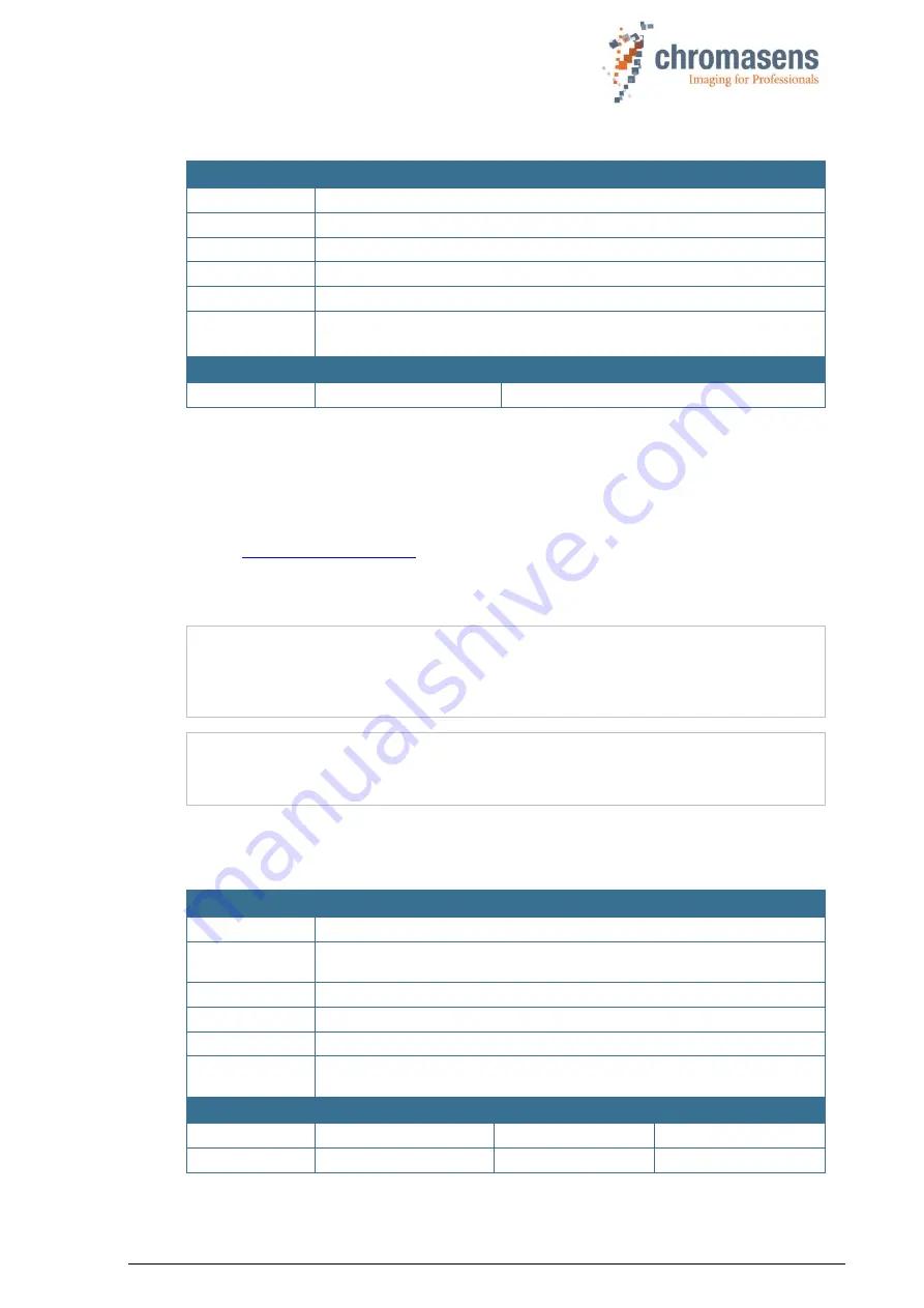
9.15.2 Setting description  


Name 

Name 

Setting description 

Function 

You can write a small description for each setting of the camera. 

Channels 

All 

Unit 

String of up to 40 characters 

Dependency 

None 

Notes 


Take notice that a carriage return counts as two characters! This may result 
in descriptions that seem to be cut by the camera. 


Camera 

Value 


All 


9.16  Tracing 

Function for debugging the system.  
Default: All options unchecked! 
For more information, ask the Chromasens support. 

E-Mail:  

[email protected] 

9.17  Line trigger and encoder setup (line synchronization) 

NOTE I 

Due  to  internal  timing  limitations,  there  is  a  small  delay  in  the  start  of  the 
integration  time  after  the  line  trigger  and  this  delay  may  jitter.  Therefore,  a 
pulsed  illumination  which  is  synchronous  to  the  trigger  signal  may  cause 
problems with image quality. 


NOTE II 

In case the camera is used in  the “Triggered Frame Scan”  mode  with active 
LineTrigger or encoder, the linesync  (Encoder or LineTrigger) has to fit some 
pulses before light barrier input. 

For detailed information about encoder setup, see section 8.6. 

9.17.1 Enable encoder 


Name 

Name 

Enable encoder 

Function 

Enables  the  line  trigger  or  encoder  mode  in  the  camera  and  the  main 
selection between internal and external line trigger. 

Channels 

All 

Unit 

Bool 

Dependency 

None 

Notes 

If  you  want  to  use  this  mode,  you  must  connect  the  external  ports  with  the 
internal function using the IO Configurator of CST. 


Camera 

Value 

Function 

Lower limit 

All 

Off / Internal 

Upper limit 

All 

On / external 

Summary of Contents for allPIXA pro

Page 1: ...allPIXA pro camera Manual CD40127 Rev 02 2018 07 12...

Page 2: ...camera 16 2 5 Sensor alignment and orientation 16 2 6 Adapter and accessories 17 2 6 1 Lenses adapters and mounts 17 2 6 3 Accessories for 4k camera S Series 18 2 6 4 Accessories for 5k 6 000px and 7...

Page 3: ...4 Preventing installation errors 40 5 4 1 Conveyor belt tracking 40 5 4 2 Perpendicularity of the sensor to the direction of transport 40 5 4 3 Rotation around the longitudinal axis of the line scan...

Page 4: ...nt automatically 84 8 2 3 Setting the operation point manually 85 8 2 4 Independent color channel white balancing 92 8 3 Generating black offset reference 93 8 3 1 Create a black offset reference inte...

Page 5: ...9 1 Integration time parameters 152 9 1 1 Integration time 152 9 1 2 Use line period 152 9 1 3 Line period time 153 9 2 Gain settings 153 9 2 1 Analog coarse gain 153 9 2 2 Current camera gain values...

Page 6: ...8 5 1 Vertical scan line reduction pattern length 178 9 8 5 2 Vertical scan line reduction pattern 178 9 9 Synchronization frame synchronization 179 9 9 1 Triggered frame scan 179 9 9 2 Scan lines aft...

Page 7: ...7 Line trigger and encoder setup line synchronization 209 9 17 1 Enable encoder 209 9 17 2 Synchronization mode 210 9 17 3 Encoder channels 211 9 17 4 Average size for the encoder 212 9 17 5 Encoder r...

Page 8: ...ty assurance monitoring Customers from all over the world of a wide range of industrial sectors have placed their trust in the experience of Chromasens in the field of industrial image processing 1 1...

Page 9: ...n image on the Camera Link corresponds to VSync HSync Horizontal synchronization Frame signal for a line corresponds to LVAL LED Light emitting diode LVAL Line valid Frame signal for a line on the Cam...

Page 10: ...pro camera Check the camera for damage which may have occurred during transport The rating plate is located on the rear of the allPIXA pro camera It shows the camera resolution and the serial number A...

Page 11: ...oller Controls and monitors the illumination unit The Chromasens Corona II illumination 3 has integrated temperature voltage sensors which can be read out with the XLC4 controller By use of the XLC4 c...

Page 12: ...e of up to 170 megapixels per second with 24 bit RGB which is equal to 510 Mbytes s With Camera Link Full_64 interface the data rate is 680Mbytes s and with Camera Link Full_80 interface the data rate...

Page 13: ...p_8Bit Mono output 2XE Mono output 1X3 85 00 MHz 20 6 KHz 41 1 KHz 50 8 KHz 50 8 KHz 50 8 KHz 41 1 KHz 50 8 KHz 75 56 MHz 18 3 KHz 36 3 KHz 48 6 KHz 48 6 KHz 50 8 KHz 36 6 KHz 50 8 KHz 61 82 MHz 15 0...

Page 14: ...ta rate on the Camera Link Base 255 Mbytes s Medium 510 Mbytes s Full_64 680 Mbytes s Full_80 850 Mbytes s Resolution 1 024 Only OEM 4 096 5120 6000 7 300 px Other sensor resolutions are available on...

Page 15: ...4 Mechanical specification 2 4 1 Mechanical dimensions of the allPIXA pro camera with 4 096 pixels The following dimensions apply to the allPIXA pro camera with 4 096 pixels Figure 2 Mechanical dimens...

Page 16: ...ur homepage http www chromasens de user NOTE II The shown position of the CCD surface is given as resulting optical value including lengthening of the sensor glass For pure mechanical calculation 0 24...

Page 17: ...system for the camera 2 6 Adapter and accessories 2 6 1 Lenses adapters and mounts Chromasens offers a large variety of accessories which are designed to provide maximum flexibility and get most out o...

Page 18: ...100 mm CP000393 01 allPIXA pro camera 4k direct mount Adapters Identification No Pos allPIXA camera F Mount Adapter CP000385 02 allPIXA camera C Mount Adapter CP000387 02 allPIXA camera 4K Adapter M42...

Page 19: ...camera Tubus 7 3k 40 mm CP000424 01 allPIXA camera Tubus 7 3k 60 mm CP000425 01 allPIXA camera Tubus 7 3k 80 mm CP000426 01 allPIXA camera Tubus 7 3k 100 mm CP000427 01 allPIXA camera 7 3k mount Adap...

Page 20: ...t is necessary to adjust the image distance with the aid of extension tubes they have to be combined and connected with grub screws Allen key size 1 5 mm maximum torque 30 Ncm Additionally it is neces...

Page 21: ...allowed housing temperature see section 2 3 Air humidity during camera operation 20 85 relative air humidity non condensing Storage transport temperature 20 C 85 C 4 F 185 F Protection category IP50 G...

Page 22: ...efore you have read all supplied documentation carefully and have understood its contents Safe and correct operation of the device requires correct and appropriate transport storage mounting and insta...

Page 23: ...knowledge of the person who is handling with have the same electrical potential 3 4 Purpose applications The allPIXA pro camera is designed for machines and systems which are used for commercial and i...

Page 24: ...defined and specified by the owner of the device in which the allPIXA pro camera is installed 3 6 Organizational measurements The instruction manual has to be stored safely in the vicinity of the cam...

Page 25: ...Before cleaning you have to switch off the device Always allow hot surfaces to cool down before cleaning the device The device works with electric power Before cleaning the device make sure that the d...

Page 26: ...AD converter The microcontroller with its RAM and flash memory supports the FPGA during image data processing to output the images through the Camera Link connector The allPIXA pro camera can be confi...

Page 27: ...ear color line scan cameras the color information is acquired with 3 x 8 bit for each image point Take notice that high quality color detection is only possible in that way Sensor pixels are 10 m wide...

Page 28: ...ed to the respective readout register Therefore the allPIXA pro camera simultaneously processes 3x2x2 channels 3 colors 2 taps and both odd and even pixels Figure 13 The allPIXA pro camera line scan s...

Page 29: ...hen sent to the frame grabber Figure 15 Process of the allPIXA pro camera image processing block diagram The CCD sensor is read out by use of a shift register The CDS correlated double sampling proces...

Page 30: ...el black level correction 1 and shading correction 2 is carried out then the image data are adjusted with the values programmed for brightness and contrast 3 Afterwards the spatial correction RGB is c...

Page 31: ...camera offers four data sets for black level correction and four data sets for shading correction Therefore you could deal with for example four different lighting systems by selecting the necessary...

Page 32: ...n is activated VidSHCOut x y VidRaw x y BRef x VidMax WRef x This calculation is done separately for all color separations RGB BRef Black Reference value for each pixel in the line WRef White Referenc...

Page 33: ...e reduced data transmission rate of the mono image the camera uses Camera Link Base mode for the transmission Output modes of 8 10 12 bit are available for monochrome image data See section 9 11 1 4 9...

Page 34: ...change of the camera s behavior is possible for different products For the user 18 settings are available Setting 19 is write protected the factory default setting is stored in setting 19 and can be...

Page 35: ...parameters of the camera can be read and modified Convenience functions for calibration of the camera are provided Calibration of the camera can be performed to adapt to current illumination conditio...

Page 36: ...power connection Hirose HR10A 7R 6P male for power supply A multi color LED for indicating the allPIXA pro camera status NOTE If you use a USB to Serial converter for the connection via RS232 it is re...

Page 37: ...allPIXA pro camera Pin no Level Description Default function 1 RS 422 GPIO_P0 input Incremental encoder high 2 RS 422 GPIO_P1 input Light barrier high 3 LVCMOS GPIO_5 BiDir PullUp Can be used for lig...

Page 38: ...o or more cameras to one sender If connection of more than one camera to one RS422 source is required additional hardware must be used Alternatively using the master slave configuration might be an op...

Page 39: ...Thermal links cooling The camera works with in the defined temperature range see sections 2 3 and 2 7 To this purpose it may be screwed to thermally conductive parts on a wide and flat surface A ther...

Page 40: ...ifferent area of the passing object Consequence is that the image generated by the three color lines is not aligned resulting in chromatic aberration which occurs laterally to the transport position F...

Page 41: ...nd the longitudinal axis of the line scan sensor chromatic aberration would occur in the image and the scale would change on the 3 color lines Chromatic aberration increases symmetrically towards the...

Page 42: ...Figure 27 you can see the optimum alignment of the camera i e it is aligned parallel to the direction of transport If the allPIXA pro camera is installed in a rotated position around the transverse a...

Page 43: ...ghting of the cables should not include the connectors one No other mechanical strain should be exerted on the connectors NOTE Grounding the housing and the outer cable shield Due to an environment wi...

Page 44: ...85 MHz The setup of camera cable and frame grabber must be tested in advance 1 Connect the Camera Link cable Camera Link Port 1 or 1 2 of the allPIXA pro camera Port 1 2 supports full data rate take...

Page 45: ...d partner account to access the software or follow the link provided by the shipment of the camera If you are not already registered request an account It is free of charge Be sure to enter valid info...

Page 46: ...t to factory defaults when you perform a firmware update Therefore it is recommended to save your own settings as backup o Click Save multiple settings to disk select a folder in the Upload Settings d...

Page 47: ...e package contains the length of the CCD sensor allPIXA camera_CCDLENGTH_Firmware_VERSION txt for example allPIXApro_7300_FW_P212 txt This file should be used in an allPIXA camera with the line length...

Page 48: ...file Download is finished when the Download List box and the Working box are closed Then the log message view of the CST displays the following message 4 Switch off the power of the camera Wait 5 seco...

Page 49: ...the desired versions Green frames indicate the current firmware CCD and FPGA versions on the camera Now the camera is ready for operation again 7 On the toolbar click Set system settings Click Send f...

Page 50: ...medium and optionally a serial interface RS232 6 1 2 Installation of the CST Software To install CST on your PC 1 Start the setup program 2 If the operating system is a 64 bit version the Version sele...

Page 51: ...he Select Additional Tasks page is shown 5 If an icon should be created on the desktop select the check box and then click Next The Ready to Install page is displayed It shows the installation paramet...

Page 52: ...on the PC desktop The Set interface parameters dialog box is shown 2 Select the PC interface for the communication either via Camera Link or external serial port 3 In the Baud rate list click the desi...

Page 53: ...e is selected in the Available matching cameras list and then click OK 6 2 CST program window The CST program window comprises 5 areas Toolbar Direct access to functions and data section 6 3 Menu bar...

Page 54: ...er settings pages for example integration time Set system configuration Transfer setting data to and from the camera Firmware update Reset the camera Open new Camera Connection Set the user level for...

Page 55: ...ce 6 4 CST menu bar The menu bar provides the following menus Figure 2 CST Menu Bar Settings Open setting from disk Open a setting from disk Useful to check a former configuration After loading a file...

Page 56: ...guration file to adapt the displayed parameters to your camera Set the user level for the CST Current camera values Display live camera values such as voltages temperatures gain values or similar This...

Page 57: ...inside the camera Set IP address If a connection to a GigE camera should be established the IP address can be set here Get current camera state With this function you can easily check the camera statu...

Page 58: ...CD40127_R02 allPIXA_pro_User Manual docx 58 6 5 Simple setup view overview Page Function Simple setup view Functions Set all basic parameters of the camera to quickly receive a well calibrated image S...

Page 59: ...1 Camera parameters This part contains the parameters related to the following Page Function Camera settings Camera Parameter Integration time Integration time Set the integration time Set the line p...

Page 60: ...tings Camera Parameter White reference mark White reference mark Set the position and size of the zone for the closed loop control Section 9 3 Camera settings Camera Parameter White control White cont...

Page 61: ...arameter Reference usage Reference usage Activate shading correction Activate black level correction Select the data set for shading and black level correction Section 9 5 Camera settings Camera Param...

Page 62: ...Camera arrangement Set the line shift spatial correction Set the scan direction Specify line suppression Section 9 7 6 6 2 Image parameter This part contains the parameters related to the image Page...

Page 63: ...slave mode Section 9 9 Camera settings Image Parameter Image processing Image processing Activate image mirroring Activate color correction Activate and set parameters for the keystone functions Secti...

Page 64: ...umination control LED flash control LED flash control LED number line pattern LED flash sequence time Pattern specification Section 9 12 6 6 4 Special functions test pattern register edit Page Functio...

Page 65: ...on the camera when the setting is burned Use this function carefully It may cause a damage of the firmware or cause malfunction of the camera Section 9 14 6 6 5 General information Page Function Camer...

Page 66: ...ection to a camera 1 On the toolbar click Show system configuration 2 In the Camera interface list click the desired camera connection 3 In the Baud rate list click a baud rate or select the Use max B...

Page 67: ...etting 19 is reserved for the backup of the default setting We recommend to use settings 1 to 9 for working settings and setting 10 to 18 for backup settings The currently selected setting is displaye...

Page 68: ...ettings to the PC For saved camera settings two different file types are available mk Files Binary file The file contents can be transferred to the camera directly set Files File in XML format Such fi...

Page 69: ...gs 2 Specify the settings that should be saved by selecting or clearing check boxes as needed 3 To specify the file name enter path and file name in the Filename box or click Browse to open a File dia...

Page 70: ...It is not allowed to delete setting 1 If setting 1 has been changed erroneously you can restore the default setting 1 by clicking Restore factory settings on the Simple setup view without having to de...

Page 71: ...On the toolbar click Show system configuration 2 In the User level list click the desired level NOTE We recommend to work with Normal user level as much as possible to avoid erroneous settings The fol...

Page 72: ...ion about camera state and the currently present errors are read and currently presented errors are cleared and acknowledged If the camera is OK the following dialog box is shown 6 18 Choosing a diffe...

Page 73: ...mory Each loading or sending of a setting overwrites the changes The intended use is for debugging the system You can edit different registers directly If you click OK register names Remark and the ad...

Page 74: ...3 Install the frame grabber on your PC by following the manufacturer s description Set the configuration of the frame grabber to adjust it to the configuration of the allPIXA pro camera For informati...

Page 75: ...to save the setting into volatile memory To specify first parameter adjustments click Show simple setup view on the toolbar Now you should be able to grab and see an image in your frame grabber tool...

Page 76: ...t important parameters and functions on the simple setup page see section 8 1 To calibrate the camera setting to your operating condition follow the steps below 1 Check your line scan system applicati...

Page 77: ...ite control is disabled For a detailed description how to perform tap balancing see section 0 5 Generate the black level reference section 8 3 On the toolbar click Start reference wizard Click Black o...

Page 78: ...functions and image enhancement functions 1 Add image processing functions You can add digital image processing functions Study the sections 9 6 to 9 10 onward to find out which image processing func...

Page 79: ...ost important parameters and functions on a single page The parameters are placed in a functional order to give you an orientation which parameters should be set first Start with the topmost parameter...

Page 80: ...on 9 17 Timing You can specify the integration time 9 1 1 If you need the line period feature see section 0 select the Use line period check box In triggered frame scan mode the camera waits for a fra...

Page 81: ...nerated simply activate deactivate them by selecting or clearing the respective check box Click Create references to start the reference wizard and follow the instructions of the wizard to generate a...

Page 82: ...Transfer setting to camera on the toolbar or press F9 Changes get lost if you select a different setting or if you reset the camera or switch it off To burn your setting permanently into the camera cl...

Page 83: ...9 2 1 8 2 1 System preparation for white and tap balancing 1 Setup Set the camera to free running mode disable encoder and frame trigger Use a white balancing reference that covers the entire scanning...

Page 84: ...the message box Possible errors White balancing error occurred Error code No 0x10D no reference data Camera is not in free running mode line and or frame but there are no trigger signals and thus no...

Page 85: ...og corase gain see section 9 2 1 6 On the toolbar click Burn setting permanently 8 2 3 Setting the operation point manually Manual operating point setting serves to determine the area which is viewed...

Page 86: ...he Enable continuous white control check box is cleared In the Position and mode for white reference mark list Automatic master detection out of area position must be selected This parameter is not vi...

Page 87: ...f the image Often this is the center of the image To check your parameter settings you can temporarily select the Display white reference borders in the image check box Note Reference mark area may no...

Page 88: ...t video levels must be set in such a way that the brightest image points are set below the saturation point Take notice that the brightest scanned reference should not bring the AD converter to satura...

Page 89: ...urrent gain value exceed 200 you could increase the corresponding value at Analog coarse gain If a current gain value is below 80 you could reduce the corresponding value at Analog coarse gain If you...

Page 90: ...ing The values for the slave tap rear tap in the example shown below are aligned with the master tap Click Refresh current camera parameters Example with the front tap as the master tap and the rear t...

Page 91: ...Enable continuous white control check box on the White control page On the White reference mark page cear the Display white reference borders in the image check box 8 Transfer settings to the camera O...

Page 92: ...White control page select Red as active channel 9 4 8 Take notice that the Select active channels for white control check boxes are only visilble if User level is set to Guru in the System configurat...

Page 93: ...ard disk 3 Prepare camera to acquire a black offset reference see section 8 3 3 Use this function if you do not have a black level reference image and want to generate a black reference with an image...

Page 94: ...ference If you don t want to perform a white balancing clear the Perform white balancing check box and continure with Step 5 Click Next The following dialog box is shown Follow the instructions in the...

Page 95: ...ttings and then click Reference usage To check black level correction select the Activate black level correction check box and check that the just updated data set is used At least a few pixels should...

Page 96: ...ary if the gain values are changed considerably 1 Start the reference wizard On the toolbar click Start reference wizard 2 Select reference type and source Click Black offset level reference Click Loa...

Page 97: ...raging each column in the selected area Click OK 5 Saving reference data In the No of data set list click the number of the data set in which the refrence data should be stored If the reference data s...

Page 98: ...for reference generation Click Transfer setting to camera to save the setting to volatile memory You may proceed to section 8 4 to generate a shading reference 8 3 3 Prepare camera to acquire a black...

Page 99: ...t performance image quality it is recommended to perform white balancing By performing a white balancing the camera gain values are set correctly to acquire the desired image for a black level referen...

Page 100: ...Select the reference file in the appearing file dialog box and then click OK Click Next 6 Define the area where the reference values should be calculated The dialog box shows the reference image On t...

Page 101: ...again active The last used setting is activated automatically Again click Next to close the wizard 8 Activate black level correction and check the result on the image On the toolbar click Show settin...

Page 102: ...You can directly perform an offset correction after grabbing the black reference The wizard guides you through this process 8 4 1 Create white gain reference internally Creation of a shading reference...

Page 103: ...erformance image quality it is recommended to perform white balancing By performing a white balancing the camera gain values are set correctly to acquire the desired image for a black level reference...

Page 104: ...in the calibration profile of the camera To avoid this if you use a static non moving white reference target use a clean white ceramic or plastic material not paper Ideally the white object should mo...

Page 105: ...ust updated data set is used Click Transfer setting to camera to save the setting to volatile memory Brightness of the newly scanned white balancing reference should be exactly at the saturation limit...

Page 106: ...er Ideally the white object should move during the calibration process because the movement results in an averaging process and the camera diminishes the effects on any small variation in the white re...

Page 107: ...by extrapolated values So the bright area is extended outwards Proceed with Step 5 Specify the area from which the reference values should be calculated in the Y position box enter the number of the f...

Page 108: ...be used Use at least 100 lines for calculation of the reference values to eliminate noise The values used for the reference are calculated by averaging each column in the selected area Sample image if...

Page 109: ...era clear the Send to camera check box To save the reference data to a file as backup select the Save to disk check box and then click Select file to specify folder and file name Click Next If the ref...

Page 110: ...ust updated data set is used Click Transfer setting to camera to save the setting to volatile memory Brightness of the newly scanned white balancing reference should be exactly at the saturation limit...

Page 111: ...te black level correction Optional Perform a white balancing Note The white reference target has to be placed in the best focus plane of the camera Therefore any features on its surface for example du...

Page 112: ...lancing By performing a white balancing the camera gain values are set correctly to acquire the desired image for a black level reference If you don t want to perform white balancing clear the Perform...

Page 113: ...ferably use a moving target to avoid wrong data due to dirt Save the image to a file and then click Next On the next page of the wizard click Select file Select the reference file in the appearing fil...

Page 114: ...ht side can also be substituted by extrapolated values So the bright area is extended outwards Proceed with Step 7 Specify the area from which the reference values should be calculated in the Y positi...

Page 115: ...the first line in the Height box the number of lines to be used Use at least 100 lines for calculation of the reference values to eliminate noise The values used for the reference are calculated by a...

Page 116: ...mera clear the Send to camera check box To save the reference data to a file as backup select the Save to disk check box and then click Select file to specify folder and file name Click Next If the re...

Page 117: ...ust updated data set is used Click Transfer setting to camera to save the setting to volatile memory Brightness of the newly scanned white balancing reference should be exactly at the saturation limit...

Page 118: ...fore grabbing the reference images according to section 8 2 4 Do not use the tap balancing function Optional Activate black level correction Do not use with the separate color channels Optional Perfor...

Page 119: ...the separate color channels see section 8 2 4 Do not use the white balancing functions of the reference wizard if you use separate color channels If you don t want to perform white balancing clear th...

Page 120: ...e illumination and save the images to disk Preferably use a moving target to avoid wrong data due to dirt Cick Next On the next page of the wizard select the Use separate images check box The page is...

Page 121: ...ull scanning range Specify the area from which the reference values should be calculated In the Y position box enter the number of the first line in the Height box the number of lines to be used Use a...

Page 122: ...to be used Use at least 100 lines for calculation of the reference values to eliminate noise The values used for the reference are calculated by averaging each column in the selected area Sample image...

Page 123: ...era clear the Send to camera check box To save the reference data to a file as backup select the Save to disk check box and then click Select file to specify folder and file name Click Next If the ref...

Page 124: ...the just updated data set is used Click Transfer setting to camera to save the setting to volatile memory Brightness of the newly scanned white balancing reference should be exactly at the saturation...

Page 125: ...XA pro camera evaluates the brightness of the respective channels in this range and compares the results with a programmable set value The amplification values for each color channel are automatically...

Page 126: ...the tap for white control Make sure that the Use sync mode check box is cleared Specify target values in the Target white reference values area If the white target is placed at the borders of the ima...

Page 127: ...et value The amplification values for each color channel are automatically adjusted Figure 34 Image synchronous operating point adjustment on the object ROI NOTE I This mode requires an frame trigger...

Page 128: ...st select the tap for white control Select the Use sync mode check box Specify target values in the Target white reference values area If the white target is placed at the borders of the image the val...

Page 129: ...2 10 For a detailed pin assignment see section 5 1 3 Also see the input level definition in section 5 1 4 8 6 2 Line trigger and encoder settings Settings for line trigger and encoder mode are edited...

Page 130: ...7 1 If no external enable signal is used select line 11 default The encoder is then controlled with the camera setting In this section only one option should be selected With Invert Input Line 14 you...

Page 131: ...nternal intelligent encoder functionality The camera measures the speed of the object and sends lines based on the defined encoder resolution and the vertical image resolution 3 In the Encoder channel...

Page 132: ...This value is calculated by the camera using the values of the specified parameters The maximum allowed value is 255 The minimum value should be at least 0 1 smaller values decrease accuracy If this v...

Page 133: ...ombined to be triggered at the same time Each flashing scenario can be defined individually as line pattern The camera provides up to four different line patterns which are executed in a sequence This...

Page 134: ...camera integration time and Camera Link speed the camera automatically increases the specific line pattern time before starting next line pattern This then also increases the required sequence time S...

Page 135: ...of the system in regard to the flash times For a detailed speed optimization sample see section 8 7 5 1 Feature scan speed optimization 8 7 2 Flash mode Image size In standard RGB mode the camera outp...

Page 136: ...amera arrangement page can be defined accordingly For the use of flash mode the parameter can be adapted according to the following procedure No of used line patterns RGB line distance value 1 1 x use...

Page 137: ...time is used for free running mode without external line trigger The sequence time defines the time for one full sequence cycle and therefore defines the transport resolution in combination with the t...

Page 138: ...canning speed Conventional camera setup 4 individual flash scenarios Integration time 100 s Required time for one full sequence 400 s allPIXA pro optimized camera setup by use of the flash function 4...

Page 139: ...ns 3 Sequence time not used in encoder mode The sequence time must be set larger than the sum of the individual line patterns NOTE One full sequence is executed per trigger signal Within such a sequen...

Page 140: ...VCMOS GPIO_P2 Out1 over 680 Ohm Pull Down 5 3 3 V over 100 Ohm Power 6 LVCMOS GPIO_P3 Out3 over 10 Ohm Pull down 7 0 V Ground 0V 8 LVCMOS GPIO_N4 Out4 over 10 Ohm Pull Down 9 RS 422 GPIO_N0 input 10 R...

Page 141: ...of interest of master slave synchronization To ensure synchronous operation the master camera provides an internal image and line trigger Line and frame trigger Spike suppression MASTER SLAVE S WhiteR...

Page 142: ...E The position of the image in transport direction Y of each camera can be set separately start and length Also the position X Y and the size of the white reference could be set separately in each cam...

Page 143: ...by input This could be done globally with or from each setting The automatic master slave detection uses the input pin assignment on the 15 pin I O connector or the CC4 bit via Camera Link The definit...

Page 144: ...two signals have to be connected 1 1 between the master and all slave camera s In addition the ground signal has to be connected between master and slave cameras Therefore pin 7 and 13 can be used fo...

Page 145: ...ace 7 0 V 0 V 0 V 8 LVCMOS Master Slave interface Master Slave interface 9 RS 422 Incremental encoder low Optional open 10 RS 422 Light barrier low Optional open 11 0 V 0 V Bridge to nSelMaster 12 LVC...

Page 146: ...E At least one ground signal pin 7 or 13 must be connected in addition to the two timing signals I O definition To enable the Master Slave interface with hub choose the appropriate input interface Wir...

Page 147: ...ration There are two basic strategies for camera frame grabber configurations to set up the system for master slave mode Option 1 Frame grabber in frame area mode preferred Frame Signal Frame trigger...

Page 148: ...running mode encoder mode Operation The frame trigger signal is sent to each frame grabber for example by the use of a dedicated connection cable So each frame grabber has the same FrameValid signal a...

Page 149: ...ix For color conversion four color conversion matrix tables are available in the camera With Offset Additional Offset in 10Bit range from 511 to 511 corresponding 0 5 to 0 5 Cxy Gain factor from 2 0 t...

Page 150: ...click Save values to save the values to the currently selected matrix NOTE The command Edit color conversion matrix is only available in CST user mode Guru 8 10 IO configuration The allPIXA camera of...

Page 151: ...lection to the camera click Transfer setting to camera on the toolbar or press F9 To save changes on the camera permanently click Burn setting permanently on the toolbar or click F10 Line trigger enco...

Page 152: ...ion 6 2 9 1 Integration time parameters 9 1 1 Integration time Name Name Integration time Function Sets the integration time in microseconds to the camera Unit Float Step 0 001 Linear Dependency None...

Page 153: ...limit All 9 25 ms 9 2 Gain settings 9 2 1 Analog coarse gain This parameter describes the coarse gain parameter of the camera which takes effect in step 1 of analog image processing section 4 5 1 Ana...

Page 154: ...Gain function to pre adjust the actual gain range Note If saturation is detected within the image clipped areas this may have different reasons One reason may be that the output signal of the CCD is...

Page 155: ...Value Lower limit All 0 Upper limit All 700 9 2 4 Update start gain values Name Name Update start gain with current gain values Function By setting and transmitting this value to the camera it update...

Page 156: ...defined absolute the reference position does not move if the width of the current scan window is changed A1 First relative pixel of white reference may be negative see section 9 3 3 A2 First absolute...

Page 157: ...rtical reference white position moves with changing Image start delay of the current scan window The height D of the white reference area is defined by Number of image lines for the white reference 9...

Page 158: ...xels of white reference 9 3 5 Use absolute horizontal position of white reference Name Name Use absolute horizontal position of white reference Function If the check box is selected absolute horizonta...

Page 159: ...er of image lines for the white reference Function Length of control zone in transport direction Channels All Unit Integer Dependency Notes If Vertical scan line reduction is used value refers to the...

Page 160: ...value for the desired value of the closed loop control for white balancing Channels Red Green Blue Odd Even Front Rear Unit Integer in 10 Bit Linear Dependency Only takes effect if the Enable continu...

Page 161: ...ge 9 4 2 Current white reference values Name Name Current white reference levels Read only Function Video value measured by the camera inside the white control mark mean value over the defined area an...

Page 162: ...In this case the camera chooses automatically which tap is used as master Changing this default behavior should only be done by experienced users Channels All Unit Integer Dependency Only takes effec...

Page 163: ...ontrol uses the maximum video level independently of the position of the white reference mark Three options are available Use sync mode If you use this option white control sets the white reference in...

Page 164: ...eference area for the brightness control appears darker than the normal paper white Therefore a missing object can irritate and misguide the automatic gain process With the paper detection functionali...

Page 165: ...ess is similar to that of the expecte object if no object is on the transport But in these cases often brightness variance of the pixels is much higher if no object is present 9 4 8 Set active channel...

Page 166: ...changes it s recommended to take a new black level reference Four reference sets for the black level correction are supported by the allPIXA pro camera as well as four reference sets for the shading c...

Page 167: ...pro camera setting All reference sets can be used for different setups for example for different f stops or different illuminations This parameter refers to the video values labeled with 2 in the diag...

Page 168: ...The internal processing is not limited up to 255 8bit This means that after the shading correction it is possible to additionally process higher values such as 300 which can be taken without loss into...

Page 169: ...aration 255 0 255 in 10Bit area 0 25 0 0 25 relative x y Number of pixels within a line or column Vid Brightness Out x y Output of this step area 0 1023 9 6 3 Contrast Name Name Contrast Function Digi...

Page 170: ...off Line delay can be set up to 5 lines With square pixel the viewing angle in transport direction could be up to 36 8 for 5 lines Camera Value CST Unit In 1 1 lines Lower limit All 0 0 Upper limit A...

Page 171: ...receive pixels in a non square shape transport resolution is not the same as the resolution in CCD direction the value of the line resolution may be lowered to the transport resolution which means th...

Page 172: ...e sequence of the lines in the direction of transport can be either red green blue RGB or blue green red BGR but the sequence can be changed if necessary Then the color offset is been corrected irresp...

Page 173: ...ard or to Backward The second encoder input or the direction input is specified using the IO Configurator in the same way as for Set by ext pin or Set by encoder direction Camera Value Lower limit all...

Page 174: ...tes Camera Value Lower limit all Suppress lines against selected direction Upper limit all Suppress lines in selected direction 9 8 Image sizes If the camera is supplied with information of the frame...

Page 175: ...wer limit All 1 Upper limit All 1 Meg for fixed object length use start condition only 64K for mixed object lenghts use start and stop condition 9 8 2 Image start delay Name Name Image start delay Fun...

Page 176: ...a of the camera The image width depends on the used video output mode for example a multiple of 2 or for some frame grabbers 8 or 16 may be needed See section 9 11 4 Camera Value Lower limit All 2 Upp...

Page 177: ...possible For most grabbers the number of camera link clock cycles and the number of pixels must be an integer value sometimes with an additional modulo of for example 8 You must test the number of pix...

Page 178: ...age Camera Value Lower limit All 0 without reduction Upper limit All 8 9 8 5 2 Vertical scan line reduction pattern Name Name Vertical scan line reduction pattern Function Defines the pattern of the f...

Page 179: ...tor NOTE II If the camera is used in Triggered Frame Scan mode with active LineTrigger or Encoder the linesync Encoder or LineTrigger must fit some pulses before light barrier input 9 9 1 Triggered fr...

Page 180: ...of scan lines Image height Sample Image acquisition is started automatically It is also possible to get a delay for a position of the light barrier before getting the scanning position c 2 Reserved Re...

Page 181: ...ee section 9 8 9 9 2 Scan lines after stop Name Name Scan lines after stop Function Sets the number of lines added to the image after the stop condition Channels All Unit Integer Dependency Only avail...

Page 182: ...example original value of 1000 lines 300 lines 2 850 lines 9 9 3 Stop after maximum number of lines Name Name Stop after max scan lines Function Stops the image if no ending edge or signal of the fra...

Page 183: ...30 9 9 5 Internal frame trigger This function permits to use a brightness change as frame trigger instead of an external light barrier The camera starts or stops image acquisition if the medium bright...

Page 184: ...ame Name Internal LB ROI length Function Specifies the ROI length Channels All Unit Dependency Takes effect only if the internal frame trigger has been activated using the IO Configurator Notes The RO...

Page 185: ...as soon as the medium values for all three colors are above the specified threshold Channels All Unit Integer Dependency Takes effect only if the internal frame trigger has been activated using the I...

Page 186: ...rent debouncing speeds to be used for the frame trigger input Channels All Unit Time see below Dependency Only active if Use start condition only or Use start and stop condition is selected The extern...

Page 187: ...start condition only and for Start and stop condition The state of the ports is checked synchronized with the line frequency clock At each rising edge of the line frequency clock the status is checke...

Page 188: ...ng edge These sequences cause a frame start at a falling edge 2 Use start and stop condition Select trigger edge detection Function These sequences cause a frame start at a rising edge and the frame s...

Page 189: ...y input If more than one camera is used for example in print inspection these cameras must be synchronized accurately to achieve the best system performance Connect line trigger frame trigger to the m...

Page 190: ...ting image This task can be done in real time inside of the camera it is usually faster than doing with the frame grabber Camera Value Function Lower limit All 0 Off Upper limit All 1 On 9 10 3 Color...

Page 191: ...ocessing step with the LUT value 1 causes a linear LUT output input which may be used For the value 0 1 a special gamma table for sRGB conversion is used See also section 8 9 For the value 0 2 a speci...

Page 192: ...Use keystone correction Function Enables the function keystone correction Channels Red Blue Unit Bool Dependency None Notes Camera Value Function Lower limit All 0 Off Upper limit All 1 On Sign negati...

Page 193: ...and last pixels relates to the nominal length of the camera 4K with a 4K allPIXA pro Camera Value CST Lower limit All 4 Upper limit All 4 9 10 8 Keystone correction width Name Name Keystone correction...

Page 194: ...ights are used Camera Value Function Lower limit All 0 Color image 3 8 Bit parallel All 1 Mono image 8 Bit on CL port 1 All 2 Mono image 10 Bit on CL port 1 Upper limit All 3 Mono image 12 Bit on CL P...

Page 195: ...l clock is not changed The minimum integration line time may be limited by this function Please see the limitations in the table mentioned below For some applications it would be helpful to increase t...

Page 196: ...a multiple of 2 All Base 3Tx8Bit 1X3 Raw Scan line length must be a multiple of 2 All Medium 2XE 2Tx24b 2XE RGB Scan line length must be a multiple of 2 All Medium 1X2 RGB RAW 2Tx24b 1X2 Raw Scan line...

Page 197: ...48 s 30 48 s 24 48 s 75 56 MHz 68 12 s 34 24 s 25 77 s 25 77 s 24 48 s 34 24 s 24 48 s 61 82 MHz 83 26 s 41 85 s 31 50 s 31 50 s 25 28 s 41 85 s 28 04 s mono output available in Camera Link Base mode...

Page 198: ...ine info block All Test ramp last line All Check sum last line All Info block in each line All Activate pixel 9 16 All Gray value sum Contrast value sum Single information is displayed in the image as...

Page 199: ...value of the actual integration time for the CCD in clocks at 100 MHz Integration times which are measured in s are IntTime 100 Up to P3 00 113 33 Px 8 MSByte Px 9 LSByte Each with the same value for...

Page 200: ...11 12 13 14 15 16 17 Value Info block GrayValSum or ContrastValue Red xFF Error register Speed2High Line time 19 16 Encoder clock 23 16 Next line pos 15 8 Time stamp 15 8 MaxVal Front R 7 0 MaxVal Rea...

Page 201: ...value is always zero Line trigger pulses line trigger active and encoder pulses encoder active are counted depending on the selected mode and can be used as position information by a sequence of docum...

Page 202: ...ide the set line length of the last line It is a value of the image s sharpness Note e g with 2048 pixels there are only 2047 difference values For ordering refer to the Contrast value sum as follows...

Page 203: ...s of each tap The number of pixels of the camera n is 4096 if you use a 4K PIXA CHK sum overwrites the LastLine test ramp on the last 2 pixels of the tap and it consists of the last 16 bits of the sum...

Page 204: ...ra Value Function Lower limit All disabled Off Upper limit All enabled On 9 12 2 LED number line pattern Parameter sets the number of patterns to be used in the LED flash control sequence The sequence...

Page 205: ...nal input LineTrigger or Encoder the frequency of the trigger signal may not be faster than the sum all active patterns For more information see section 8 7 Multi channel flash control Camera Value Lo...

Page 206: ...ra Link cable Name Name Generate test pattern Function Enables different test images in the camera Channels All Unit Integer Dependency None Notes The data are generated directly after analog image pr...

Page 207: ...pattern level and one live image Test pattern 5 Gray value with parameter Test pattern level Test pattern 6 15 Internal use only 9 13 2 Test pattern level Name Name Set test pattern level Function Se...

Page 208: ...hanges get lost You can find this function in CST at the command Register edit of the Advanced menu It is possible to damage the function of the camera by use of this function Therefore this function...

Page 209: ...n the start of the integration time after the line trigger and this delay may jitter Therefore a pulsed illumination which is synchronous to the trigger signal may cause problems with image quality NO...

Page 210: ...ollowing two modes are available Line trigger With the line trigger the camera sends one line per pulse Encoder mode The camera measures the distance of the signals and sends lines with the requested...

Page 211: ...ST Camera Value All 1 Channel full step 1 edge per step All 1 Channel encoder 2 edges per step All 2 Channel encoder 4 edges per step The following three modes are available 1 One Channel full step 1...

Page 212: ...All No averaging 2 4 8 Upper limit All 16 9 17 5 Encoder resolution Name Name Encoder resolution Function Sets the distance of which the transport might be moved by one increment of the encoder Chann...

Page 213: ...e in transport resolution accuracy This value is automatically calculated with one of the following formulas by the user defined values in CST 25 4 1000 By using dots per inch dpi for this calculation...

Page 214: ...trigger after the set value of signals from external line trigger source Channels All Unit Integer Dependency Only available if the Enable encoder check box is selected Notes Camera Value Lower limit...

Page 215: ...rence mark Automatic Automatic Automatic Automatic 9 4 5 White control mode Use sync mode Off Off Off Off Stop gain control if level Off Off Off Off Stop gain control by variance Off Off Off Off 9 4 6...

Page 216: ...10 7 Pixel shift for correction 0 0 0 0 9 10 8 Keystone correction width 1 1 1 1 9 11 1 Video output mode 3x8 Bit 3x8 Bit 3x8 Bit 3x8 Bit 9 11 2 Color weights 0 3 0 59 0 11 0 3 0 59 0 11 0 3 0 59 0 11...

Page 217: ...9 3 7 First image line for the white reference X X X 9 3 8 Number of image lines for the white reference X X X 9 3 9 Number of reference samples Average X X X 9 3 10 Show white reference border X X X...

Page 218: ...ed and blue color channel X X X 9 10 3 Color conversion X X X 9 10 4 Select active CCM X X X 9 10 5 Gamma correction X X X 9 10 6 Use keystone correction X X X 9 10 7 Pixel shift for correction X X X...

Page 219: ...MA number To obtain an RMA number contact Chromasens support first Chromasens GmbH Max Stromeyer Stra e 116 D 78467 Konstanz Germany Phone 49 0 7531 876 0 Fax 49 0 7531 876 303 E Mail info chromasens...

Page 220: ...for example if the temperature is above the allowed maximum value Camera state is subdivided into four groups of four bits with the following meaning Bits 15 12 Bits 11 8 Bits 7 4 Bits 3 0 If continuo...

Page 221: ...ack from step 2 to normal operation 1 Let the camera cool down 2 Check the environment and improve cooling if necessary 3 Restart the camera power off on For information about temperature level defini...

Page 222: ...r after start during operation at a specific action please describe How often did problem occurs once always regularly rarely please describe Did the application ever run ok yes no If known describe t...

Page 223: ...Chromasens CD40127_R02 allPIXA_pro_User Manual docx 223 11 Appendix 11 1 EC conformity declaration...

Page 224: ...cipal main plain distance from data sheet of the lens First calculate the magnification After getting the result for the magnification calculate the object to image distance by following Calculate the...

Page 225: ...late the needed distance rings you must get some information about the optical setup Optical parameter Real focal length from data sheet Image distance calculated Parameters of the lens Back flange le...

Page 226: ...60 0 mm This covers flange distances from 97 526 mm up to 122 56 mm 11 2 3 Determining line period time and integration time The relationship between the line frequency and the line period time is as...

Page 227: ...r Manual docx 227 Chromasens GmbH Max Stromeyer Stra e 116 Phone 49 7531 876 0 www chromasens de 78467 Konstanz Fax 49 7531 876 303 info chromasens de Germany CD40127_R02 allPIXA_pro_User Manual docx...

Reviews: