background image

Programmable AC Source 61601/61602/61603/61604 Quick Start Guide 

equal to the maximum current rating of the AC source.    Do not use three 
separate wires to connect power to the input of the AC source. Do the 
following things one by one: 
 

1. 

Remove the safety cover from the back of the AC source. 

2. 

Screw the power cord to the terminal blocks of the AC source as 
follows: 

Green or green/yellow wire to the terminal labeled “G”. 
White or blue wire to the terminal labeled “N”. 
Black or brown wire to the terminal labeled “L”. 

3. 

Slip the safety cover over the ac input terminal strip, and secure the 
cover with two screws. 


WARNING

  To protect the operators, the wire connected to the GND 

terminal must be connected to the earth ground.   
Under no circumstances shall this AC source be 
operated without an adequate ground connection. 

 
Installation of the power cord must be done by a professional and in 
accordance with local electrical codes. 


2.4  Power-on Procedure 

WARNING

  Before turning on the instrument, all protective earth 

terminals, extension cords, and devices connected to 
the instrument must be connected to a protective earth 
ground. Any interruption of the protective earth 
grounding will cause a potential shock hazard that could 
result in personal injury. 

 
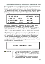
Apply the line power and turn on the power switch on the front panel.    The 
AC source will do a series of sel tests.    The LCD on the front panel will 
light up and display as below:     


SELF TEST     

                            WAIT . . . . . .   


2-2 

Summary of Contents for 61601

Page 1: ...Programmable AC Source 61601 61602 61603 61604 Quick Start Guide...

Page 2: ...Programmable AC Source 61601 61602 61603 61604 Quick Start Guide Version 1 0 February 2010 P N A11 001328...

Page 3: ...not be held liable for errors contained herein or direct indirect special incidental or consequential damages in connection with the furnishing performance or use of this material CHROMA ATE INC 66 Hw...

Page 4: ...illed at cost Chroma assumes no responsibility for its product being used in a hazardous or dangerous manner either alone or in conjunction with other equipment High voltage used in some instruments m...

Page 5: ...ceeds the threshold level specified in the standards of SJ T 11363 2006 and EU 2005 618 EC 1 Chroma is not fully transitioned to lead free solder assembly at this moment however most of the components...

Page 6: ...v...

Page 7: ...t off the internal or external protective grounding wire or disconnect the wiring of protective grounding terminal Doing so will cause a potential shock hazard that may bring injury to a person FUSES...

Page 8: ...ol indicates that the terminal must be connected to ground before operation of equipment WARNING The WARNING sign denotes a hazard It calls attention to a procedure practice or the like which if not c...

Page 9: ......

Page 10: ...de ix Table of Contents 1 Introduction 1 1 1 1 Names of Parts 1 1 1 1 1 Front Panel 1 1 2 Installation 2 1 2 1 Inspection 2 1 2 2 Preparation for Use 2 1 2 3 Requirements of Input Power 2 1 2 3 1 Rati...

Page 11: ......

Page 12: ...es accurate stable output voltage and frequency The PWM design of power stage allows for full volt ampere into loads The front panel has both RPG rotary pulse generator and keypad controls for setting...

Page 13: ...ill make the LCD display switching between MAIN PAGE and CHOICE PAGE Or change to CHOICE PAGE in each functional list Under shift mode pressing this key on MAIN PAGE the uses can save the output setti...

Page 14: ...ELP Numeric and decimal keys The user can program numeric data by pressing the digital keys and the decimal key Under shift mode pressing acts the HELP function The LCD display will show more informat...

Page 15: ......

Page 16: ...AC line input Then since it is intelligently cooled by fans it must be installed in sufficient space for circulation of air It should be used in an area where the ambient temperature does not exceed...

Page 17: ...otect the operators the wire connected to the GND terminal must be connected to the earth ground Under no circumstances shall this AC source be operated without an adequate ground connection Installat...

Page 18: ...shown on 6 2 in Programmable AC Source 61601 61602 61603 61604 User s Manual The test item 3 REMOTE shows EMPTY if the option board with GPIB and RS 232 is not connected After finishing memory data a...

Page 19: ...urce 61601 61602 61603 61604 Quick Start Guide Waiting more than 3 seconds is suggested to turn on power after turning off For more detail information please see the User s Manual in the CD attached t...

Page 20: ......

Page 21: ...Programmable AC Source 61601 61602 61603 61604 Quick Start Guide 6...

Reviews: