Christopeit Sport 1129 Assembly And Exercise Instructions Download Page 21

21

English

Training instructions

You must consider the following factors in determining the amount of training 
effort required in order to attain tangible physical and health benefits:
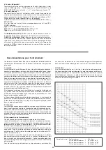
1. Intensity:
The level of physical exertion in training must exceed the level of normal 
exertion without reaching the point of breathlessness and / or exhaustion. 
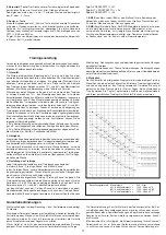
A suitable guideline for effective training can be taken from the pulse rate. 
During  training  this  should  rise  to  the  region  of  between  70%  to  85%  of 
the maximum pulse rate (see the table and formular for determination and 
calculation of this).
During the first weeks, the pulse rate should remain at the lower end of this 
region, at around 70% of the maximum pulse rate. In the course of the follo-
wing weeks and months, the pulse rate should be slowly raised to the upper 
limit of 85% of the maximum pulse rate. The better the physical condition 
of the person doing the exercise, the more the level of training should be 
encreased to remain in the region of between 70% to 85% of the maximum 
pulse rate. This should be done by lengthening the time for the training and 
/ or encreasing the level of difficulty.
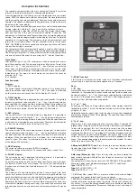
If the pulse rate is not shown on the computer display or if for safety reasons 
you wish to check your pulse rate, which could have been displayed wrongly 
due to error in use, etc., you can do the following:
a. Pulse rate measurement in the conventional way (feeling the pulse at the 
wrist, for example, and counting the number of beats in one minute).
b. Pulse rate measurement with a suitable specialised device (available from 
dealers specialising in health-related equipment).

2.Frequency
Most experts recommend a combination of health-conscious nutrition, which 
must be determined on the basis of your training goal, and physical training 
three times a week. A normal adult must train twice a week to maintain his 
current level of condition. At least three training sessions a week are required 
to improve one’s condition and reduce one’s weight. Of course the ideal 
frequency of training is five sessions a week.

3. Planning the training
Each training session should consist of three phases: the warm-up phase, 
the training phase, and the cool-down phase. The body temperature and 
oxygen intake should be raised slowly in the warm-up phase. This can be 
done with gymnastic exercises lasting five to ten minutes.
Then the actual training (training phase) should begin. The training exertion 
should be relatively low for the first few minutes and then raised over a period 
of 15 to 30 minutes such that the pulse rate reaches the region of between 
70% to 85% of the maximum pulse rate.
In order to support the circulation after the training phase and to prevent 
aching or strained muscles later, it is necessary to follow the training phase 
with a cool-down phase. This should be consist of stretching exercises and 
/ or light gymnastic exercises for a period of five to ten minutes.
You find further information on the subject warm-up exercises, stretch exer-
cises or general gymnastics exercises in our download area under www.
christopeit-sport.com

4. Motivation
The key to a successful program is regular training. You should set a fixed 
time and place for each day of training and prepare yourself mentally for the 
training. Only train when you are in the mood for it and always have your goal 
in view. With continuous training you will be able to see how you are progres-
sing day by day and are approaching your personal training goal bit by bit.

Calculation formula:  Maximum pulse rate 

=  220 - age 


(220 minus your age)


90% of the maximum pulse rate 

=  (220 - age) x 0.9


85% of the maximum pulse rate 

=  (220 - age) x 0.85


70% of the maximum pulse rate 

=  (220 - age) x 0.7

Summary of Contents for 1129

Page 1: ...leitung für Bestell Nr 1129 Assembly and exercise instructions for Order No 1129 Montage en bedieningshandleiding voor Bestellnummer 1129 D GB NL RU Notice de montage et d utilisation du No de commande 1129 F Инструкция по монтажу и эксплуатации заказа 1129 ...

Page 2: ...werden ersetzen sie diese umgehend und sichern sie das Gerät gegen Benutzung solange es noch nicht in Stand gesetzt wurde 9 Bei der Einstellung von verstellbaren Teilen auf die richtige Position bzw die markierte maximale Einstellposition und ordnungsgemässe Sicherung der neu eingestellten Position achten 10 Sofern in der Anleitung nicht anders beschrieben darf das Gerät nur immer von einer Person...

Page 3: ...3 Deutsch ...

Page 4: ...4 ...

Page 5: ...ppe oval 2 7 36 1129 10 BT 10 Verkleidung links 1 1 11 36 1129 01 BT 11 Verkleidung rechts 1 1 10 36 1129 02 BT 12 Schraube M4x20 4 10 11 36 9805 42 BT 13 Schraube M4x25 6 1 10 11 36 9805 43 BT 14 Rundstopfen 2 69 36 1129 11 BT 15 Stützrohr 1 1 33 1129 04 SI 16 Handhebelachse 1 1 21 27 33 1129 05 SI 17 Handgriff links 1 21 33 1129 06 SI 18 Handgriff rechts 1 27 33 1129 07 SI 19 Griffknauf 2 17 18 ...

Page 6: ... 39 9960 74 Tretkurbelachse 1 80 33 1129 18 SI 75 Spannrolle 1 74 36 1129 26 BT 76 Magnet 1 75 36 9824 27 BT 77 Federring für M6 4 73 39 9865 CR 78 Selbstsichernde Mutter M6 5 73 87 39 9816 VC 79 Sicherungsring C17 2 74 36 9805 32 BT 80 Kugellager 6203 2 1 74 36 9805 31 BT 81 Pulssensoren 2 50 36 9126 06 BT 82 Kunststoffscheibe 10 22 2 66 36 9718 33 BT 83 Sensorhalter 1 40 36 9814 21 BT 84 Schraub...

Page 7: ...men 1 1 Montieren Sie den vorderen Fuß 2 mit den vormontierten Transpor trollen 97 am Grundgestell 1 Benutzen Sie dafür je zwei Schrauben M8x25 4 gebogene Unterlegscheiben 8 22 6 und Federringe 5 Schritt 2 Montage des hinteren Fußrohres 7 am Grundrahmen 1 1 Montieren Sie den hinteren Fuß 7 mit den höhenverstellbaren Schrau ben 8 am Grundgestell 1 Benutzen Sie dafür 4 Schrauben M8x25 4 gebogene Unt...

Page 8: ...dalarm 70 und schrauben Sie diesen mittels der Schraube M8x20 24 dem Federring 5 und der Unterlegscheibe 23 am Pedalarm 70 fest 2 Stecken Sie den Fußschalenhalter rechts 49 in die Aufnahme des rechten Fußhebels 30 und schrauben Sie die beiden Teile mittels der Verbindungsplatte 31 der Schraube M8x20 24 den Schrauben M8x15 25 den Unterlegscheiben 6 der Kunststoffscheibe 23 und den Federringen 5 fes...

Page 9: ...est montieren Schritt 6 Montage der Handgriffe 17 18 an den Verbindungsrohren 21 27 1 Die Handgriffe 17 18 auf die Verbindungsrohre 21 27 stecken und die Bohrungen in den Rohren so ausrichten dass sie übereinander liegen Achtung Die Griffrohre müssen nach der Montage so ausgerichtet sein dass die oberen Enden nach außen vom Stützrohr 15 weg gebogen sind 2 Die Schrauben 25 mit einem Federring 5 und...

Page 10: ...uerst einen Fuß von der Fußschale für einen sicheren Stand auf den Boden und danach den zweiten Fuß und steigen Sie zu einer Seite über das Gerät ab Dieses Fitnessgerät ist ein stationäres Heimsportgerät und simuliert eine Kombination aus Radfahren Steppen und Laufen Ein vermindertes Risiko besteht durch ein wetterunabhängiges Training ohne äußere Einflüsse sowie bei evtl Gruppenzwang das Risiko v...

Page 11: ...verbrauchten Kalorien angezeigt Eine Vorgabe eines bestimmten Wertes mittels der und Taste ist möglich Ist eine bestimmte Verbrauchsmenge vorgegeben so wird die noch zu verbrau chenden Kalorienmenge angezeigt Wird der vorgegebene Wert erreicht wird dieses durch ein akustisches Signal angezeigt Eine Speicherung der zuletzt erreichten Werte in dieser Funktion erfolgt Höchstgrenze der Anzeige 9990 Ka...

Page 12: ...kühl Phase eingehalten werden In dieser sollten fünf bis zehn Berechnungsformeln Maximalpuls 220 Alter 90 des Maximalpuls 220 Alter x 0 9 85 des Maximalpuls 220 Alter x 0 85 70 des Maximalpuls 220 Alter x 0 7 Garantiebestimmungen Die Garantie beginnt mit dem Rechnungs bzw Auslieferdatum und beträgt 24 Monate Während der Garantiezeit werden eventuelle Mängel kostenlos beseitigt Bei Feststellung ein...

Page 13: ...necessary repairs WARNING Replace the worm parts immediately and keep this equipment out of use until repaired 9 When setting the adjustable parts observe the correct position and the marked maximum setting positions and ensure that the newly adjusted position is correctly secured 10 Unless otherwise described in the instructions the machine must only be used for training by one person at a time T...

Page 14: ...17 44 33 1129 08 SI 22 Plastic bushing 18 15 21 27 30 44 49 36 9824 22 BT 23 Washer 8 28 6 24 39 10180 24 Allen head screw M8x20 10 16 44 49 70 96 39 10454 25 Allen head screw M8x15 14 15 17 18 44 49 39 9888 CR 26 Washer curved 8 19 4 25 39 10232 27 Connection tube right 1 18 49 33 1129 08 SI 28 Pedal tube left 1 29 33 1129 09 SI 29 Pedal tube bracket 2 70 33 1129 10 SI 30 Pedal tube right 1 29 33...

Page 15: ... 54 75 36 1129 25 BT 73 Hex head bolt M6x18 4 74 75 39 9960 74 Axle for pulley 1 80 33 1129 18 SI 75 Pulley 1 74 36 1129 26 BT 76 Magnet 1 75 36 9824 27 BT 77 Spring washer for M6 4 73 39 9865 CR 78 Nylock nut M6 5 73 87 39 9816 VC 79 Clip C17 2 74 36 9805 32 BT 80 Bearing 6203 2 1 74 36 9805 31 BT 81 Hand pulse 2 50 36 9126 06 BT 82 Plastic washer 10 22 2 66 36 9718 33 BT 83 Sensor bracket 1 40 3...

Page 16: ...e front stabilizer 2 at main frame 1 1 Attach the front foot 2 with preassembled transport rollers 97 to the main frame 1 Do this with the two screws M8x25 4 curved washers 8 22 6 and spring washers 5 Step 2 Attach the rear stabilizer 7 at main frame 1 1 Attach the rear foot 7 with height adjustable foot screws 8 to the main frame 1 Do this with the 4 screws M8x25 4 curved washers 8 22 6 and sprin...

Page 17: ...pedal tube 30 onto the pedal crank 70 and tighten it with screw M8x20 24 washer 23 and spring washer 5 at the pedal crank 70 firmly 2 Push the pedal bracket right 49 into the holder of right foot tube 30 and tighten it with screws M8x15 25 screw M8x20 24 steel plate for pedal 31 spring washer 5 washer 6 and plastic washer 23 firmly 3 Install the left pedal tube 28 with all additionally required pa...

Page 18: ...with washers 26 and spring washers 5 through the holes and tighten the handgrip bars 17 18 at connection tubes 21 27 firmly Step 7 Attach the pulse grip bar 50 at handlebar support 15 1 Place the pulse grip bar 50 to the support 15 and push the pulse cable 53 through the hole of support 15 into inner top position 2 Put the pulse grip bar 50 against the support 15 sothat the holes are aligned Push ...

Page 19: ...f you like to exercise the upper body too you can place the hands from fixed handle bar to the left and right handle grips d Then you can increase the pedaling speed gradually and adjust braking resistance levels to increase the exercise intension e Keep always your hands on fixed handle bar or hand grips left and right Dismount a Slow down the pedaling speed until it comes to rest b Keep the hand...

Page 20: ...attained by this function are stored Limit of the display 9990 calories 5 RPM display The current revolution per minute RPM is displayed This value change automatically all 5 seconds and shows current Puls 6 PULSE display The current pulse rate is displayed in beats per minute It is possible to specify a particular value using the or key If a particular upper pulse rate limit has been specified an...

Page 21: ... your training goal and physical training three times a week A normal adult must train twice a week to maintain his current level of condition At least three training sessions a week are required to improve one s condition and reduce one s weight Of course the ideal frequency of training is five sessions a week 3 Planning the training Each training session should consist of three phases the warm u...

Page 22: ... celui ci et sûr cet équipement de l utilisation jusqu à réparé 9 Pour le réglage des pièces faire attention à régler la bonne position ou la position de réglage maximale marquée et à bloquer correctement la nouvelle position réglée 10 Si rien d autre n est indiqué dans le mode d emploi l appareil ne doit être utilisé que par une personne pour l entraînement Le temps d entraînement ne devait pas d...

Page 23: ... 44 49 70 96 39 10454 25 Vis à tête bombèe et collet carrè M8x15 14 15 17 18 44 49 39 9888 CR 26 Rondelle intercalaire 8 19 4 25 39 10232 27 Tube de junction droite 1 18 49 33 1129 08 SI 28 Logement gauche du sabot 1 29 33 1129 09 SI 29 Ètrier logement du sabot 2 70 33 1129 10 SI 30 Logement droit du sabot 1 29 33 1129 01 SI 31 Plaque de connexion 2 44 49 36 1129 12 BT 32 Vis à tête bombèe et coll...

Page 24: ... 1 54 75 36 1129 25 BT 73 Vis hexagonal M6x18 4 74 75 39 9960 74 Axe de pédalier 1 80 33 1129 18 SI 75 Roulette de serrage 1 74 36 1129 26 BT 76 Aimant 1 75 36 9824 27 BT 77 Bague ressort pour M6 4 73 39 9865 CR 78 Ecrou indesserrable M6 5 73 87 39 9816 VC 79 Bague de sécurité C17 2 74 36 9805 32 BT 80 Roulement à billes 6203 2 1 74 36 9805 31 BT 81 Unité à poignée de mesure du pouls 2 50 36 9126 ...

Page 25: ... avant 2 aux roulettes de transport 97 sur le corps de l appareil 1 Servez vous des 2 vis M8x25 4 rondelles intercalaires 8 22 6 et rondelle élastique bombée 5 Etape n 2 Montage du pied arrière 7 sur le cadre de base 1 1 Attachez le pied arrière 7 avec des vis variable de hauteurs 8 au corps de l appareil 1 Utilisez à cet effet 4 vis M8x25 4 les rondelles intercalaires 8 22 6 et les rondelles élas...

Page 26: ... abîmer le câble Etape n 4 Montage des logements de sabot 28 30 au manivelle de pédales 70 1 Emboîtez l extrémité du logement de sabot droit 30 sur le manivelle de pédale 70 et vissez ce dernier à l aide de la vis M8x20 24 à l aide de la rondelle 23 et du ressort élastique 5 sur le bras de pédale 70 2 Emboîtez le ètrier de sabot droite 49 dans le logement droit du sabot 30 et vissez les deux pièce...

Page 27: ...es vers l extérieur du tube de support 15 2 Introduire les boulons bruts à brut à tête bombée et collet carré 25 à travers les trous de forage à rondelles 26 et rondelles élastique bombée 5 et serrer à bloc Etape n 7 Montage du poignee de pouls 50 sur le tube de support 15 1 Dirigez le poignée de pouls 50 contre de tube de support 15 et s ils dirigent le câble de pouls 53 par le forage 2 Vissez la...

Page 28: ...es repose pieds alternant votre poids corporel sur les deux repose pieds c Si vous voulez également entraîner la partie supérieure du corps placez vos mains sur les poignées mobiles au lieu de la poignée fixe d Ensuite augmentez graduellement la vitesse et modifiez la résistance afin d intensifier l exercice e Tenez toujours vos mains sur la poignée fixe ou sur les poignées mobiles Descendre a Ral...

Page 29: ...u à présent Affichage limité au maximum à 9990 calories 5 Affichage RPM affichage RPM Permet d afficher la actuelle récupération par minute Cet affichage est un double affichage pour RPM et Pouls 6 Affichage PULS affichage du pouls Permet d afficher le pouls actuel par battement par minute La touche et permet de fixer préalablement une valeur déterminée Lorsqu une flèche dirigée vers le haut s all...

Page 30: ...nt proprement dit phase d entraînement devant commen cer ensuite Choisir une faible résistance pendant quelques minutes puis accroître entre 15 et 30 minutes de sorte que le pouls se situe entre 70 et 85 de son maximum Afin de faciliter la circulation après la phase d entraînement et d éviter des courbatures ou des muscles noués la phase d entraînement doit être suivie d une phase de ralentissemen...

Page 31: ...sluitend van originele reserveonderdelen gebruik maken Waarschuwing Delen moeten worden warm voor het gebruik van de beveiligingsinrichting overdreven vervanging van dit meteen en u zult krijgen De beveiligingsinrichting tegen het gebruik zolang het nog niet in cabine is vastgesteld 9 Bij de instelling van verstelbare onderdelen op respectievelijk de correcte positie of de gemarkeerde maximale ins...

Page 32: ...25 BT 34 Onderlegplatje 8 16 4 32 39 10018 CR 35 Zelfborgende moer 4 32 98 39 9818 36 Rol 2 28 30 36 1129 13 BT 37 Kogellager 6002 4 36 36 1129 14 BT 38 Vastzetring C15 4 96 36 1129 15 BT 39 Bowdenkabel 1 42 61 36 1129 16 BT 40 Sensorkabel 1 41 36 1129 17 BT 41 Verbindingskabel 1 40 43 36 1129 18 BT 42 Weerstandinstelling 1 15 39 36 1129 19 BT 43 Computer 1 15 36 1129 03 BT 44 Voetvatopname links ...

Page 33: ...3 SW 72 Flakke riem 1 54 75 36 1129 25 BT 73 Zeskantschroef M6x18 4 74 75 39 9960 74 Krukarmas 1 80 33 1129 18 SI 75 Spanrol 1 74 36 1129 26 BT 76 Magneet 1 75 36 9824 27 BT 77 Veering voor M6 4 73 39 9865 CR 78 Zelfborgende moer M6 5 73 87 39 9816 VC 79 Vastzetring C17 2 74 36 9805 32 BT 80 Kogellager 6203 2 1 74 36 9805 31 BT 81 Handpulseenheid 2 50 36 9126 06 BT 82 Kunststofschijf 10 22 2 66 36...

Page 34: ...p 1 Montage van de voorste voet 2 aan het basisframe 1 1 Monteer de voorste poot 2 met de vooraf gemonteerde transportrollen 97 op het onderstel 1 Gebruik daarvoor 2 bouten M8x25 4 gebogene tussenringen 8 22 6 en veerringen 5 Stap 2 Montage van de achterste voet 7 aan het basisframe 1 1 Monteer de achterste poot 7 met de schroef voor hoogte Compensatie 8 op het onderstel 1 Gebruik daarvoor 4 boute...

Page 35: ...oeven M8x20 24 de ringen 23 en de veerring 5 op de pedaalkruk 70 vast 2 Stopt u het voetvatopname rechts 49 in de opname van de rechter voetsteunen 30 en schroeft u beide delen middels de verbindingsplaat 31 de schroeven M8x15 25 de schroef M8x20 24 de ringen 6 de ringen 8 28 23 en de veerringen 5 vast 3 De linker voetsteun 28 incl alle toebehorende delen aan de linker zijde van het apparaat preci...

Page 36: ...bogen 2 De schroef 25 met de veerring 5 en der onderlegplatje 26 verzien en door de openingen steken en de greepbuitzen 17 18 op de ver bindings buizen 21 27 vastdraaien Stap 7 Montage van het handgreep 50 aan de steunbuis 15 1 Breng de handgreep 50 naar de steunbuis 15 en steek de stekker van de Polskabel door de gaten van den steunbus 15 en plaatz de kabel aan bowenzijde uit de steunbuis 2 Voorz...

Page 37: ...an links naar rechts te verplaatsen c Als u ook het bovenlichaam wilt trainen kunt u uw handen in plaats van op het vaste stuur op de beweegbare handvaton aan de linker en rechterkant d Om de intensiteit van de training te verhogen kunt u de pedaleersnelheid verhogen of de weerstand op het apparaat verhogen e Houdt uw handen altijd ofwel op de vaste stuur ofwel op het linker en rechter handvat Afs...

Page 38: ...N weergave De actuele stand van het aantal verbruikte calorieën wordt weergegeven Een bepaalde waarde kan worden ingesteld met behulp van de en toets Wanneer het aantal te verbruiken calorieën is ingesteld wordt het aantal nog te verbruiken calorieën weergegeven Wanneer de ingestelde waarde wordt bereikt wordt dat door een akoestisch signaal weergegeven De laatst bereikte waarde bij deze functie w...

Page 39: ...uten zo toenemen dat de hartslag zich tussen de 70 en 85 van de maximale hartslag bevindt Om de bloedsomloop na de trainingsfase te ondersteunen en om spierpijn of verrekte spieren te voorkomen moet de trainingsfase door een cooling down worden gevolgd Hierbij moeten vijf tot tien minuten lang stretchoefeningen en of lichte gymnastiekoefeningen worden gedaan Voor meer informatie over uitoefening v...

Page 40: ...и срочны и они еще не гарантируют устройство против использования до тех пор пока это в состоянии были помещены 9 Настраивая регулируемые детали следить за правильным положением или соотв учитывать помеченную максимальную позицию настройки и обеспечивать надлежащую фиксацию заново настроенного положения 10 Если в руководстве не указано иного то тренажером может пользоваться только один человек Вре...

Page 41: ...олт с внутренним шестигранником M8x15 14 15 17 18 44 49 39 9888 CR 26 Изогнутая шайба 8 19 4 25 39 10232 27 Соеденительная труба правый 1 18 49 33 1129 08 SI 28 Рычаг ноги правый 1 29 33 1129 09 SI 29 Держатель ножного рычага 2 70 33 1129 10 SI 30 Рычаг ноги левый 1 29 33 1129 01 SI 31 Диск связи 2 44 49 36 1129 12 BT 32 Болт с внутренним шестигранником M8x50 2 28 29 30 39 9811 33 Подшипник скольж...

Page 42: ...9 25 BT 73 Шестигранный болт M6x18 4 74 75 39 9960 74 Ось кривошипа 1 80 33 1129 18 SI 75 прясть рулон 1 74 36 1129 26 BT 76 Магнит 1 75 36 9824 27 BT 77 Шайба пружинная Для M6 4 73 39 9865 CR 78 Г айка самострахующаяся M6 5 73 87 39 9816 VC 79 Кольцо стопорное C17 2 74 36 9805 32 BT 80 Подшипник 6203 2 1 74 36 9805 31 BT 81 Датчик пульса 2 50 36 9126 06 BT 82 Подшипник 10 22 2 66 36 9718 33 BT 83...

Page 43: ...олик 97 на основную раму 1 Используйте для этого по два болта M8x25 4 две подкладные шайбы 8 22 6 и две пружинные шайбы 5 Шаг 2 Монтаж ножек 7 на основную раму 1 1 Смонтируйте заднюю ножку 7 с bинт регулировки высоты 8 на основную раму 1 Используйте для этого по два болта M8x25 4 две подкладные шайбы 8 22 6 и две пружинные шайбы 5 По сле того как Вы смонтировали весь тренажер правильно выстави те ...

Page 44: ...и пружинной шайбы 5 2 Вденьте крепление Фиксатор стопы левый 49 в правый Рычаг ноги левый 30 и закрутите их винтом M8x20 24 Болт с внутрен ним шестигранником M8x15 25 Диск связи 31 шайбы 23 шай бы 6 и пружинной шайбы 5 3 Монтаж левого Рычаг ноги 28 произвести также как описано в пункте 1 2 только с учетом левой стороны Шаг 5 Монтаж Соеденительная труба 21 27 и крепление Фиксатор сто пы 44 49 1 Ось...

Page 45: ...ся так чтобы верхние части расхо дились от опорной трубы 15 2 Вставьте болты 25 в отверстия и крепко прикрутите рукоятки 17 18 с Подкладная шайба 26 и пружинные шайбы 5 Шаг 7 Монтаж рукоятки 50 на опорную трубу 15 1 Ведите хватание 50 к опорной трубе 15 и поместите кабель пульса 53 бурением 2 Вставьте на болты M8x25 4 одну пружинную шайбу 5 и подклад ную шайбу 6 и крепко прикрутите рукоятку 50 к о...

Page 46: ...новременной тренировки верхней части тела держитесь за движущиеся поручни справа и слева С увеличением или уменьшении скорости и тормозного сопротивления можно регулировать интенсивность тренировки Постоянно держитесь за скобу или поручни во время тренировки Спускаться с тренажера Прекратите тренировку крепко держась за неподвижные поручни Снимите сначала одну ступню с педали и поставьте ее надежн...

Page 47: ...тся посредством акустического сигнала Производится сохранение последних достигнутых параметров для данной функции Верхняя граница показаний 990 калорий 5 Функция RPM КОЛИЧЕСТВО ОБОРОТОВ ПЕДАЛЕЙ Производится индикация количества оборотов педалей в минуту в режиме постоянной смены с показателем пульса приблизительно каждые 5 секунд 6 Функция ПУЛЬС Производится индикация фактического состояние пульса...

Page 48: ...инут Затем приступайте к основной фазе тренировки Нагрузка должна быть относительно низкой в первые несколько минут а затем возрастать в течение 15 30 минут чтобы частота пульса была в пределах 70 85 от максимальной Для того чтобы поддержать циркуляцию крови после основной фазы тренировки предупредить возникновение болей или напряжения в мышцах необходима заключительная фаза тренировки выполнение ...

Reviews: