background image

   Connect Devices

D4K3560 Setup Guide

31

020-101161-05 Rev. 1 (06-2015)

Select a video source

After connecting a video source to the projector, you must select it using the touch panel controller 
(TPC).

1. On the TPC, select 

Input > Channel

.

2. Scroll the list of channels until you find the channel that best matches your configuration.

3. Tap the channel.

An image appears on the screen. If an image does not appear on the screen, repeat steps 1 to 
3, selecting a different channel.

Connect a computer or server

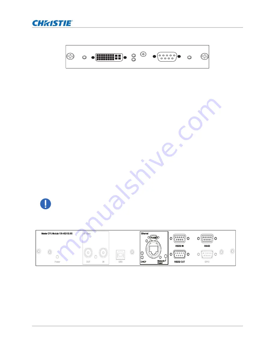
To communicate with a remote computer, server or an existing network, use an RJ-45 cable to 
connect the Ethernet hub or switch to the Ethernet port, located on the projector MCPU faceplate. 
When using the Christie serial protocol over Ethernet, connect to port 3002.
For applications or equipment using serial communications, use the Christie-proprietary serial 
protocol to communicate with the RS422 port or the RS232 ports on the MCPU faceplate. 

Set up Ethernet

Ethernet is setup to obtain an IP address automatically if a DHCP server is on the network. To 
modify IP settings, or manually enter an address.

Notice.

 Failure to comply with the following may result in property damage.

The RS232 port located on the MCPU faceplate uses Christie-proprietary protocol and is intended for 
Christie accessories or automation controllers only. For more information on the serial commands, 
see the 

D4K-60 Serial API Commands Technical Reference (P/N: 020-101258-XX)

.

Dual Link DVI Input

PWR

Analog

Digital

2 - VGA

1 - Dual Link DVI-I

Signal

Summary of Contents for D4K3560

Page 1: ...D4K3560 S e t u p G u i d e 020 101161 05...

Page 2: ...g Problems or damage caused by improper installation alignment or by equipment modification if by other than Christie service personnel or a Christie authorized repair service provider h Problems or...

Page 3: ...bol means that electrical and electronic equipment at their end of life should be disposed of separately from regular waste Please dispose of the product appropriately and according to local regulatio...

Page 4: ...omponents 14 Position the projector 15 Install the lamp power supply in a rack stand 15 Connect the lamp power supply 17 Configuring ballast settings for 200 VAC operation 20 Configuring ballast setti...

Page 5: ...t a video source using HDMI 30 Connect a video source using DVI 30 Select a video source 31 Connect a computer or server 31 Set up Ethernet 31 D4K3560 signal connectivity 33 Operation 34 Projector LED...

Page 6: ...injury Never look directly into the projector lens or at the lamp The extremely high brightness can cause permanent eye damage For protection from ultraviolet radiation keep all projector housings in...

Page 7: ...hnician is required for all installations SHOCK HAZARD Never operate the projector without all of its covers in place Use of the projector s rear safety strap is mandatory to prevent the projector fro...

Page 8: ...personal injury or property damage Always wear manufacturer approved protective safety clothing gloves jacket face shield when the lamp door is open or when handling the lamp Only qualified technician...

Page 9: ...um of 10 minutes before performing maintenance or service procedures Indicates the presence of an electrical shock hazard To avoid personal injury always disconnect all power sources before performing...

Page 10: ...ation and directions See the product service manual for specific information and directions Never look directly into the projector lens The extremely high brightness can cause permanent eye damage Ind...

Page 11: ...a minimum of 450 CFM ft 3 min external exhaust airflow to ensure adequate cooling of the Xenon arc lamp at less than or equal to 25 C 77 F ambient and less than 3 000 ft 914 4 m elevation Above 25 C...

Page 12: ...icators on page 34 C Manual douser override Closing the douser rotates a shutter blade in front of the lamp and reduces the lamp power to 2 0 kW to conserve lamp life The override is for emergency use...

Page 13: ...the projector For a list of available lenses see the D4K3560 User Manual P N 020 101075 XX I Air filter cover and air filter Filters the intake air before it circulates through the front compartment...

Page 14: ...more D Projector interlock and communication connections Provides communication between the projector and the LPS E DC lamp power cables Carries power from the LPS to the projection lamp F Lamp break...

Page 15: ...you may have to forfeit some aim and stay more perpendicular to the screen In such cases some lens offset can reduce the keystone distortion 2 Position the lamp power supply LPS so its cables reach t...

Page 16: ...w duct directly behind the LPS 8 Insert airflow duct into rack stand from the outside 9 Secure airflow duct to rack stand using screws from the rack stand panels 10 When installing other components in...

Page 17: ...cross connections between projectors and lamp power supplies always perform this procedure in its entirety for each projector one after another Never attempt to connect multiple projectors and lamp p...

Page 18: ...rear lens side cover 5 Ensuring AC power is off at the supply connect the AC directly to the LPS AC input terminal block according to your region For North America Japan Korea and most of Central Sou...

Page 19: ...e to comply with the following may result in property damage Internal input line voltage switch setting must match AC available on site Warning Failure to comply with the following could result in dea...

Page 20: ...a Phillips screwdriver 3 Insert the convenience outlet harness black wire into the first position on the terminal block 4 Tighten the screw to secure the harness in place Ensure the wire insulation is...

Page 21: ...a Philips screwdriver 3 Insert the convenience outlet harness black wire into the second position on the terminal block 4 Tighten the screw to secure the harness in place Ensure the wire insulation is...

Page 22: ...ition of the projector requires more adjustment than the standard feet allow two 6 inch extension rods can be installed to increase the amount of available adjustment Install the foot extension rods 1...

Page 23: ...the touch panel controller TPC to the connector on the rear panel of the projector 4 Adjust the TPC angle for optimal viewing then tighten the mounting arm lock securely so that the TPC is held in pla...

Page 24: ...projector as this may introduce some vibration into the image Remove the projector shroud The lens side shroud must be removed to gain access to the lens The other shroud must be removed when connecti...

Page 25: ...rs Warning Failure to comply with the following could result in death or serious injury Keep fingers and other body parts away from the moving parts in the projector Motors and fans may start without...

Page 26: ...C calibration process Touch panel controller The touch panel controller TPC is a touch sensitive screen Use the TPC to control the projector manage sources adjust the display and view status informati...

Page 27: ...ow shows the video option card slot numbers and the MCPU panel Input signal devices are connected to the video option cards and the option card slot numbers are important for some types of input signa...

Page 28: ...eft most Slot 3 2 In Bottom left 2 Slot 4 1 In Top right 3 Slot 4 2 In Bottom right 4 Four Port input configuration Four cards Quadrants Columns Slot 1 1 In Top left 1 left most Slot 2 1 In Top right...

Page 29: ...or column of a 4K input image This configuration supports high resolution and high frame rate input video streams Two or four TDPIC cards Two Port Enables connection of two DisplayPort cables to two...

Page 30: ...orts high resolution and high frame rate input video streams Two THIC cards One Port Enables connection of one HDMI cable to the 1 IN input of a THIC card in any slot In this configuration the HDMI in...

Page 31: ...e projector MCPU faceplate When using the Christie serial protocol over Ethernet connect to port 3002 For applications or equipment using serial communications use the Christie proprietary serial prot...

Page 32: ...tap Menu Configuration Ethernet Settings Modify IP Settings 2 Set the network information for the projector To obtain information automatically from the network tap Automatic To manually enter the ne...

Page 33: ...TDPIC 2 X X Four Port 4K QHD 24 25 30 48 50 60 HDMI 1 4a 2x THIC 4 X X X X X X Four Port 4K QHD 24 25 30 48 50 60 3G SDI 2x3GIC 4 X Two Port 4K QHD 24 25 30 48 50 60 DVI Dual 2xDDIC 2 X Four Port 4K...

Page 34: ...On Video electronics are on the lamp is on Solid Yellow Standby mode Video electronics are off lamp is off Solid Green Yellow and Red AC is on MCPU board software has not started initialization Flash...

Page 35: ...tap the Home tab 2 Tap Power Action Event Projector LEDs MCPU Board Power LED Applying AC power to the projector head Solid red Solid green Solid yellow Yellow Within the first second Solid red Solid...

Page 36: ...Seoul ph 82 2 702 1601 Japan Tokyo ph 81 3 3599 7481 India ph 91 080 6708 9999 Germany ph 49 2161 664540 France ph 33 0 1 41 21 44 04 Eastern Europe and Russian Federation ph 36 0 1 47 48 100 China Sh...

Reviews: