


9
machine’s surface.
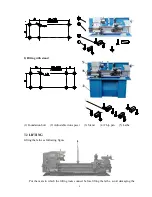
The lathe net weight is 330kg, stand weight is 60kg. When lifting, must keep the machine
in balance and avoid tilting.
The carriage, tailstock and other slide parts of the lathe are locked before leaving factory.
Don’t loosen these when lifting and should inspect to confirm whether they are locked or not in
order to prevent the parts sliding to make danger. Carefully put the machine on the base or stand
which have been fixed and fix the machine to the base or stand by bolt and nut.
7.3 CLEANING
Prior to shipment all machine and finished surfaces are coated to prevent rusting. Before
moving the carriage or tailstock, use clean solvent to remove the rust preventive coating, use
brush and solvent to clean the lead screw, rack, feed -rod, etc. Move the saddle, carriage and
tailstock to cleaned direction about 300mm, clean the ways for any residue of rust preventive
coating. Move the other way the same distance and repeat the process. Such care in the cleaning
will ensure the removal of any foreign particles and prevent the way scoring.
Lubricate the ways when clean finished.
8. LEVELING
The lathe should be kept perfectly level at all times.
LEVELING PROCEDURE:
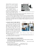
A. Longitudinal leveling
After the bed-
ways are dry after cleaning, back off the base screws, place a 6” precision
machinist spirit level over working table along longitudinal direction ( bed length direction )
move the working table at the headstock end along bed length direction, make leveling by
adjusting the adjustable iron spacer, obtain a reading. Then move the working table to the
tailstock, adjust the screw of the adjustable iron spacer until the spirit level obtain the same
reading as on the headstock end.
put the spirit level on the headstock end put the spirit level on tailstock end
B. CROSS LEVELING
Put the spirit level on the working table alo ng cross direction ( bed width direction ), move
the working table to the headstock end along bed length direction, take a reading, then move the
working table to the tailstock end, the reading at this end must be exactly the same as the other
end. No twist is permissible. If the reading is not same, adjust the screw of the adjustable iron
Summary of Contents for CZ1224
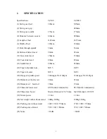
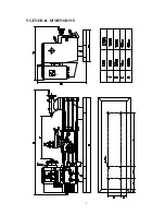
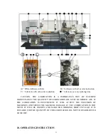
Page 7: ...6 5 GENERAL DIMENSIONS ...


