www.chipsee.com
www.chipsee.com
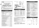
Pin 1
CAN2_H
CPU CAN Channel 2 H signal
Pin 2
CAN2_L
CPU CAN Channel 2 L signal
Pin 3
CAN1_H
CPU CAN Channel 1 H signal
Pin 4
CAN1_L
CPU CAN Channel 1 L signal
Pin 5
RS485_2-
CPU UART2, RS485 -(A) signal
Pin 6
CPU UART2, RS485 +(B) signal
Pin 7
RS485_5-
CPU UART5, RS485 -(A) signal
Pin 8
CPU UART5, RS485 +(B) signal
Pin 9
RS485_4-
CPU UART4, RS485 -(A) signal
Pin 10
CPU UART4, RS485 +(B) signal
Pin 11
RS232_3_RXD
CPU UART3, RS232 RXD signal
Pin 12
RS232_3_TXD
CPU UART3, RS232 TXD signal
Pin 13
RS232_1_RXD
CPU UART1, RS232 RXD signal
Pin 14
RS232_1_TXD
CPU UART1, RS232 TXD signal
Pin 15
GND
System Ground
Pin 16
+5V
5V Power Output, No more than
1A Current output.
ATTENTION:
UART2 signal has been used by Bluetooth signal on board.
1.
The RS485_2 function has been disabled by default. If
customer needs to use RS485_2 function, please contact
us, we will disable the Bluetooth function.
All the CAN signal and RS485 signal are not mounted on
2.
the 120Ohm matched resistance.
Summary of Contents for CS10768F097E-C111
Page 1: ...www chipsee com www chipsee com PPC EPC A9 97 C User Manual Release 1 0...
Page 2: ...www chipsee com www chipsee com...
Page 8: ...www chipsee com www chipsee com Figure 1 Top View Android...
Page 9: ...www chipsee com www chipsee com Figure 2 Back View CS10768F097P...
Page 10: ...www chipsee com www chipsee com C111 Figure 3 Top View Android...
Page 26: ...www chipsee com www chipsee com...


